Attiny85 + speed sensor + 7seg display = HEADACHE

I’m trying to build an old-school 7-segment display to show speed, based around an Attiny85, a MAX7219, and a choice of magnetic sensor - either an A3144 Hall sensor, or a reed switch.

I built a prototype with a Nano and a reed switch, and it worked. Now I’m trying to rebuild that with an Attiny, and simply can’t get any meaningful reading from either type of sensor on either of the two input pins I have available.

Here’s the circuit diagram:

And here’s the stripped-down dummy code I’m using:

// THIS WORKS WHEN GROUNDING PIN 3 AS A BUTTON
//COUNTS UP TO 1023 (A23) WHEN NO BUTTON ATTACHED

#include "LedControl.h"

LedControl lc=LedControl(0,2,1,1);
int ledRefreshRate=500; //rate in millis to update the screen
int time;
unsigned long delaytime=250;
const int buttonPin = 3;

int buttonPushCounter1 = 0;    // counts the button pushes
int buttonState1 = 0;    // tracks the button state
int lastButtonState1 = 0;    // last state of the button
int buttonState = 0;  // Button status
int lastButtonState = LOW;  //Button set to LOW
long lastDebounceTime = 0;  // Debounce status
long debounceDelay = 50;  // Debounce timer

void setup() {

  lc.shutdown(0,false);
  lc.setIntensity(0,8);
  lc.clearDisplay(0);
  pinMode(buttonPin, INPUT);  // Sets button as input

}

void printNumber(int v) {  
    int ones;  
    int tens;  
    int hundreds; 
    boolean negative=false;

 //   if(v < -999 || v > 999)  
  //      return;  

    if(v<0) {  
        negative=true; 
        v=v*-1;  
    }

    ones=v%10;  
    v=v/10;  
    tens=v%10;  
    v=v/10; hundreds=v;  

    if(negative) {  
        //print character '-' in the leftmost column  
        lc.setChar(0,0,'-',false);  
} 

    else {
        //print a blank in the sign column  
        lc.setChar(0,0,' ',false);  
    }  
    //Now print the number digit by digit 
    if (millis() - time >= ledRefreshRate)
    {
        time = millis();
      if (!hundreds == 0) {
        lc.setDigit(0,1,(byte)hundreds,false);
      }
      lc.setDigit(0,2,(byte)tens,false); 
      lc.setDigit(0,3,(byte)ones,false); 
    }
} 

void loop() {
  // All the debound button press stuff
  int reading = digitalRead(buttonPin);
  buttonState1 = digitalRead(buttonPin);

  if (reading != lastButtonState) {
    lastDebounceTime = millis();
  } 


  if ((millis() - lastDebounceTime) > debounceDelay) {
    if (reading != buttonState) {
      buttonState = reading;

        if (buttonState1 != lastButtonState1) {

          if (buttonState1 == HIGH) {
            buttonPushCounter1++;
            
            if (buttonPushCounter1 == 1023) {
              buttonPushCounter1 = 1;}

          }

          else {
          }

        }
          lastButtonState1 = buttonState1;

    }
  }
  lastButtonState = reading;
printNumber(buttonPushCounter1);
}

EXPECTED BEHAVIOUR:
whenever the reed switch or hall sensor detect the presence of a magnet, the display should increase the count (buttonPushCounter1) by 1.

ACTUAL BEHAVIOUR:

Depending on how I connect the reed switch or the Hall sensor, the numbers on the Arduino either count infinitely up to the maximum value on their own, with no input from the sensor, or the arduino STOPS counting the moment the sensor detects a signal.

I seem to be making a fundamental error with either digitalread or analogread (the Hall sensor board supports both) in combination with whatever weirdness the ATTINY85 has on the two pins I have available - PB3 and PB4.

At this point I’m open to any and all suggestions because I’m tearing my hair out. I don’t think I can even get Serial comms on the board because I’m using those pins to communicate with the MAX7219.

For reference, this is the Hall sensor:

And this is the reed switch:

The display has naked LEDs, each of which requires a series current limiting resistor to protect both the MCU and the display from destruction.

As a rule of thumb, a port pin can conduct 20 mA safely. Avoid exceeding that, especially for the MCU pins connected to the display common cathode pins.

Show how your button is wired. Using a pulldown resistor for LOW when nominal/"released?"

MAX7219 has curent setting mechanism through resistor R1 for the regulation of the brightness of small-sized display devices. There is no threat either to MCU or MAX7219 as to causing any harm to them.

Is PB5 configured as /RESET or just another I/O pin?

Also, your schematic seems to show Vcc on the ATtiny connected to ground. Or possibly nothing; any time I've used a bus in KiCad I've used net labels on any connections to it. Does that schematic pass ERC?

I would suggest you to collect the following ATTiny85 Devopment board, and you comfortably build your project.

PB5 isn’t in use.
Thanks for highlighting the bad connection for Vcc - I’ve fixed that now. This was the first time I’ve ever used KiCad so it’s a steep learning curve for me.

I can see. That wasn't the question. The question was how is it configured?

I don’t know how to answer that question. It’s not connected and there’s nothing in the code.

It's either configured as the /RESET pin (in which case it's floating, and that is bad), or it's configured as GPIO. It's one or the other. Which is it?

At this point, you know as much as I do. I bought the chip, I fitted it to the breadboard, wired it to the diagram above and uploaded the provided code. I don’t know how to “configure” either of the options you say, unless you can point me in the right direction to find the answers.

EDIT: What I can say is, I’ve uploaded other, more simple sketches to cycle digits on the display to check for stability, and it runs for hours with no issues. So I presume it’s not a floating RESET.

That's not true. I have no idea what you've configured the fuse settings to, what you're using to program the chip, what your physical setup looks like, etc., etc. Absent basic, necessary, information, all I can do is wish you good luck with your project.

All I can do is apologise for not being able to provide you with the information you need, and all I can ask is for a modicum of patience for a beginner who clearly doesn’t have your experience with these things.

It’s a basic off-the-shelf attiny85, being programmed in the Arduino IDE using an Arduino Nano as ISP. If things like the behaviour of PIN5 or the fuse or other things you mention can be configured, then I haven’t encountered that and any pointers you can give, other than your best wishes, would be much appreciated.

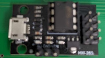
Thank you. I do have a digispark and, if there’s no other practical advice given in this thread, then I’ll rebuild a new version around that board and see if I can fix the issue myself.

Yes, with the button method I used a 10k pull-down resistor, but I’ve also experimented with the built-in pullup resistor and at this point I can barely remember what worked and what didn’t.

Do you get expected behavior from your sketch if you use a button switch as input instead of the Hall effect sensor and reed switch?

When you use a core with Arduino such as ATTinyCore, it is a good idea to Burn Bootloader using Nano as ISP on the target MCU (ATtiny85) so that will set the fuses. Then you can upload the sketch to the MCU using the Nano as ISP.

You may enjoy EasyEDA Pro online edition and there are some tutorial videos on using it. For me it didn’t have a huge learning curve.

If PB5 has had the fuses set such that reset is disabled, you can’t upload via ISP until you enable reset with the fuses again, via a simple high voltage programmer. You may find your Digispark has reset disabled and PB5 is a GPIO pin. If that is the case you will need to upload via the micronucleus bootloader that is on it, or change the fuses to upload via ISP.

I do not see the second reed switch on Pin 2 (PB3) in the code in Post #1.

Your debounce seems to be different from what I have become accustom. It seems to set a second state, and read the button more than one time. Would you try this button-debounce in your sketch? (check that I used your variable names in this code chunk...

You will need to make another variable bool lastButtonREAD;

void buttonpressstuff() {
  bool reading = digitalRead(buttonPin); // read button pin
  if (reading != lastButtonREAD) { // if THIS read is not the same as LAST read
    lastDebounceTime = millis(); // start a timer
    lastButtonREAD = reading; // store current state
  }
  if ((millis() - lastDebounceTime) > debounceDelay) { // if button change was longer ago than debounce timeout...
    if (reading == HIGH && buttonState == LOW) { // ... and button is PRESSED and state is RELEASED
      buttonPushCounter++; // VALID BUTTON PRESS... increase counter
      if (buttonPushCounter1 == 1024) // constrain buttonPushCounter1
        buttonPushCounter1 = 1; // reset buttonPushCounter1
    }
    buttonState = reading; // update button state
  }
}

When you use a core with Arduino such as ATTinyCore, it is a good idea to Burn Bootloader using Nano as ISP on the target MCU (ATtiny85) so that will set the fuses. Then you can upload the sketch to the MCU using the Nano as ISP.

You may enjoy EasyEDA Pro online edition and there are some tutorial videos on using it. For me it didn’t have a huge learning curve.

If PB5 has had the fuses set such that reset is disabled, you can’t upload via ISP until you enable reset with the fuses again, via a simple high voltage programmer. You may find your Digispark has reset disabled and PB5 is a GPIO pin. If that is the case you will need to upload via the micronucleus bootloader that is on it, or change the fuses to upload via ISP.

This is all very valuable information and much appreciated. I don’t remember burning the bootloader on this chip but since I’m uploading via ISP then I guess I didn’t disable the Reset pin.

Would you try this button-debounce in your sketch?

Thank you for this! First I tried with a button (plus a 4k7 pullup resistor), then with the reed switch which has its own 10k pullup. There’s instabilities, but I was able to see enough expected behaviour from the button and reed that I now think the fault is in the wiring, which is causing the input pin to float occasionally.

Thank you to everyone who provided positive input!

I hope to join you soon with Digispark Board. I have experinece working with this. The attached file may be helpful for you.

Please, post the sketch that has worked with your NANO Board.

Are your ATtiny85s brand new?

Which version of Digispark Board you own Fig-1 or Fig-2?


Figure-1:


Figure-2:

Ch-19 ATtiny85 MCULec (4).pdf (919.3 KB)
Ch-19 ATtiny85 MCUText.pdf (1.2 MB)

Hi, @Grrrmachine
Why do you want to go to an Attiny85, a Nano has basically the same footprint as a Nano, so could fit behind it or a Pro Mini, its 328 core?

Tom.... :smiley: :+1: :coffee: :australia: