Hi guys I am running this code on an Attiny85 but it keeps failing after a week or so. Sometimes it can be re-programmed but sometimes it fails altogether and requires replacement.
This is the code which works perfectly:
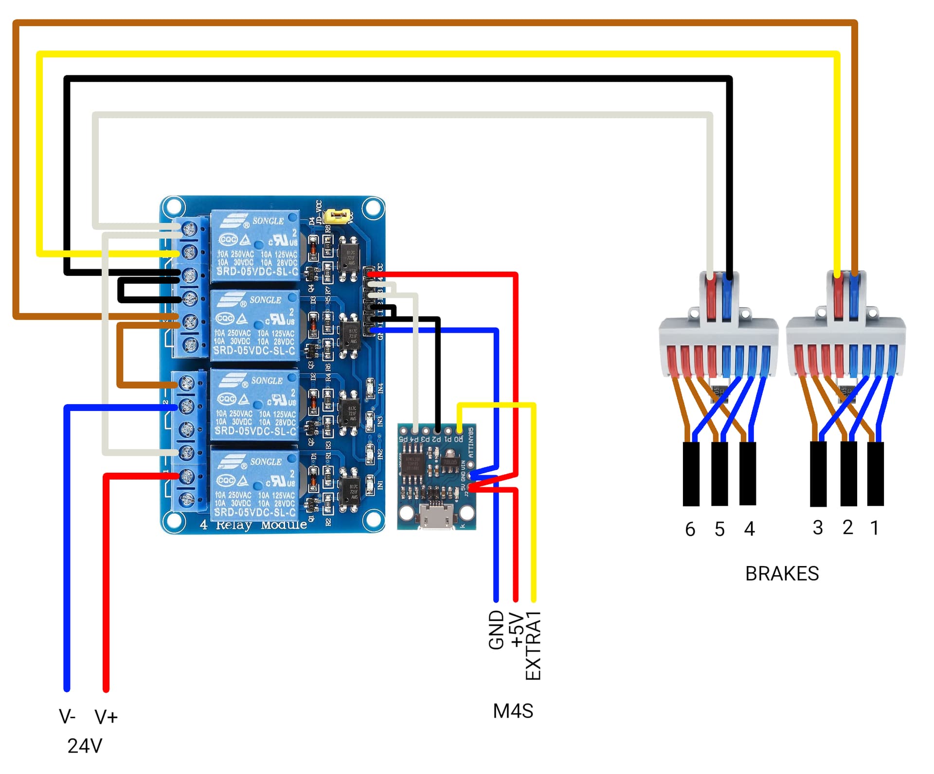
`Use code tags to format code for the forum`// Attiny85 program for power reduction of electromagnetic motor brakes.
// See http://tvdr.de/sim/3/brakes.htm.
// Provided as is, without any warranty. Free as in beer.
// Author: Klaus.Schmidinger@tvdr.de.

// I/O pins:

#define pCtl PB0 // connects to the control line of the M4S controller
#define pLed PB1 // controls the onboard LED (on if M4S control is low)
#define pPwr PB2 // connects to IN1+IN2 of the relais board
#define pXcg PB4 // connects to IN3+IN4 of the relais board

// Timing:

#define ReleaseTime 1000 // ms

// Globals:

bool BrakesReleased = false;
bool PowerReduced = false;
unsigned long ReleaseStart = 0;

void RelaseBrakes(void)
{
  digitalWrite(pPwr, LOW);
  digitalWrite(pXcg, LOW);
  BrakesReleased = true;
  PowerReduced = false;
}

void EngageBrakes(void)
{
  digitalWrite(pPwr, HIGH);
  digitalWrite(pXcg, HIGH);
  BrakesReleased = false;
}

void ReducePower(void)
{
  digitalWrite(pXcg, HIGH);
  PowerReduced = true;
}

void setup()
{
  // I/O pins:
  pinMode(pCtl, INPUT_PULLUP);
  pinMode(pLed, OUTPUT);
  pinMode(pPwr, OUTPUT);
  pinMode(pXcg, OUTPUT);
  digitalWrite(pLed, LOW);
  digitalWrite(pPwr, HIGH);
  digitalWrite(pXcg, HIGH);
}

void loop()
{
  if (digitalRead(pCtl) == HIGH) {
     digitalWrite(pLed, LOW);
     EngageBrakes();
     }
  else if (!BrakesReleased) {
     digitalWrite(pLed, HIGH);
     RelaseBrakes();
     ReleaseStart = millis();
     }
  else if (!PowerReduced) {
     if (millis() - ReleaseStart > ReleaseTime) {
        ReducePower();
        }
     }
}

 Any idea why it keeps failing?
Please correct your post and add code tags around your code.
There is a small pencil below your existing posts.
click on this pencil ➜ that will let you edit your post.
Select the part of the text that corresponds to the code
Click on the <code/> icon in the toolbar to indicate that it is code
click Save Edit
(Also make sure to properly indent the code in the IDE before copying and pasting it here. This can be done by pressing ctrlT on a PC or cmdT on a Mac)
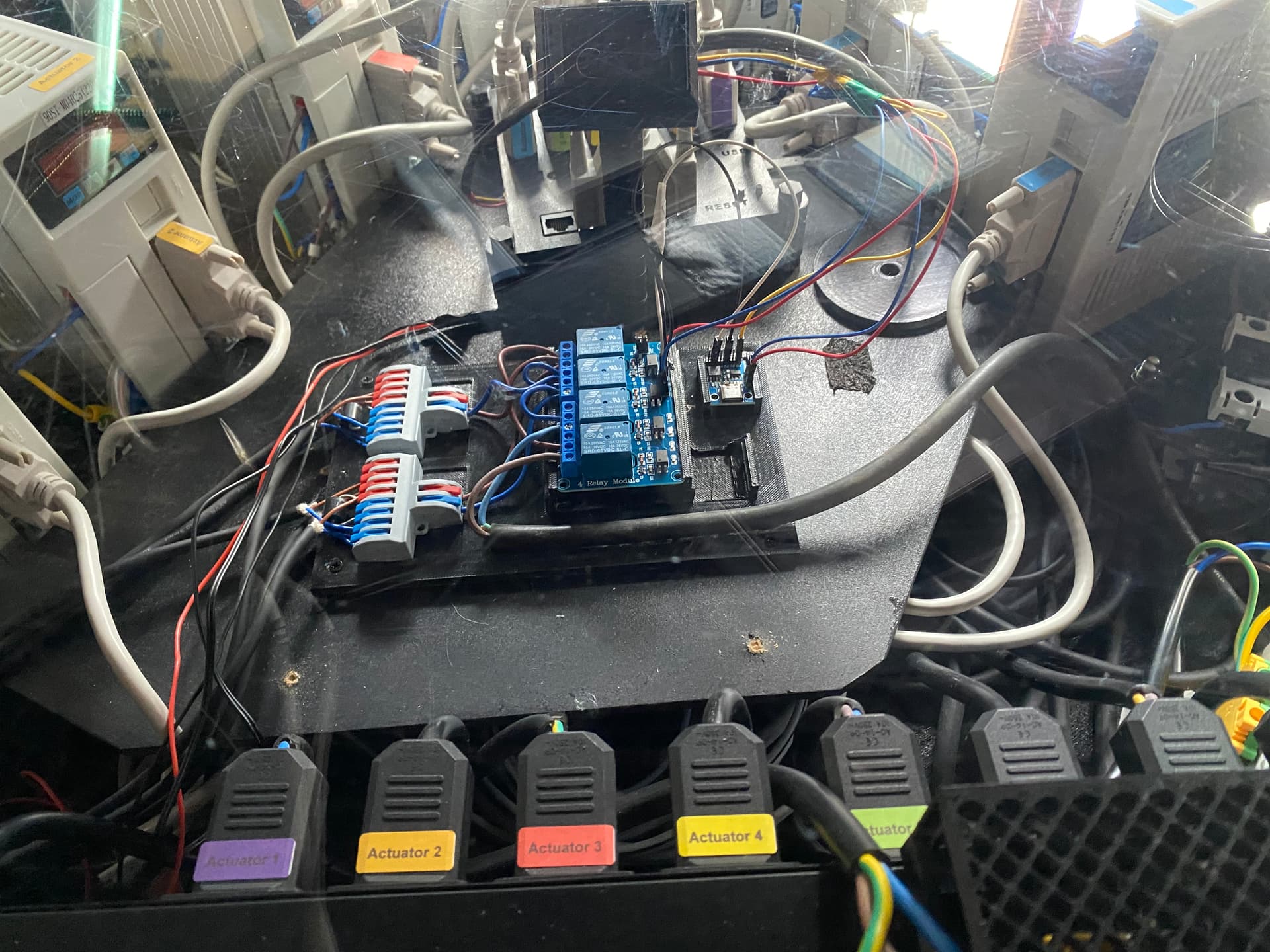
Tell us about your circuit, power etc.. The code you shared is straightforward and would not damage the chip by itself. The issue is almost certainly electrical or hardware-related.
➜ relay board does not have proper flyback diodes ?
➜ weak regulator, insufficient decoupling, or long wires with power supply to the ATtiny85 which dips or spikes when the relay engages ?
➜ relay module inputs expecting a heavy sink/source current (some boards need >20 mA on each input), overstressing the MCU's pins ?
...