PeterH:
The first relay board you listed looks fine for this job.
You will need to connect the I/O pins on the relay board with the corresponding header pins/sockets on your Arduino. You will need to have / make / buy the appropriate wires to do this. Male-to-male jumper wires are commonly available for solderless breadboad projects and not expensive, or you can make up your own from the appropriate size wire. To connect to those male header pins you can either use a female header connector for temporary use, or just solder the wire on for a permanent connection. (If soldering, this is best done by somebody who is experienced at soldering electronic components.) If you need to connect multiple devices to the 5V header then you can do that just by connecting one wire to the header and then splicing it to feed both devices.
Alright I think I'm getting the hang of this
This is the image of the relay module
So here's my understanding of it. I will connect the VCC on the module to the 5V on the arduino, Connect the GND on the module to the GND on the arduino, and connect the IN1 or IN2 (I have to use only one?) To any of the digital outputs ports on the arduino.
I then connect my pump to the VOC/VOC and GND Connections available on the other side of the module.
I then run a sketch that tells the arduino to turn "on" the specific port the module is connected to.
Would that be it? Would turning "On" the port be enough? The way I Imagine it is, when the arduino is told to turn on this port, it sends a small current through it, this current is run through the relay which amplifies the current and then runs that back to the pump which turns the pump on.
Would I be correct in assuming all this? (Came up with all this with a little research on the net)
Also, I think I will use a breadboard that connects the 5V on the arduino to one of the connected breadboard lines, and connect the sensor and the relay to that same line.
Thanks again guys
And thanks for the tips Rahere, I think simplifying my problem down is the way to go, especially for a beginner like me
Yes that is how you would operate the relay. The relay just acts as a switch, so you will need to wire it up to the power supply and pump so that when the relay is closed there is a circuit between the pump and the power supply.
@Rahere, what you say is correct for a real product, but I think well outside the brief for this project (I gather it's just to be displayed to a class) and also well outside Kando's ability at present. Also proper failsafe and fault detection can double or even triple the hardware required, Kando is worried about the cost of an extra diode
PeterH:
Yes that is how you would operate the relay. The relay just acts as a switch, so you will need to wire it up to the power supply and pump so that when the relay is closed there is a circuit between the pump and the power supply.
Wait, So do I need another power supply? Or in my case is the arduino (connected to either a 9V or a computer via USB) the power supply?
@Graynomad, No no I don't mind spending for a diode (they're cheap aren't they?) The thing is, connecting a relay via the diode solution looks a bit complicated for my level of knowledge atm, So the relay module (which is essentially the entire circuit I need) Is the easier route.
I just need to finish up this school project for this week, after that Im dwelling into arduino because I think I'm really into the whole thing (Expect alot more annoying noob posts from me )
Yes, you need a power supply for the pump which supplies the voltage and current that the pump needs. This is going to be taking massively more current than the Arduino can provide or handle and none of that will come from or through the Arduino - it is a completely separate circuit which is just switched on and off by the Arduino using the relay.
Yes, you need a power supply for the pump which supplies the voltage and current that the pump needs. This is going to be taking massively more current than the Arduino can provide or handle and none of that will come from or through the Arduino - it is a completely separate circuit which is just switched on and off by the Arduino using the relay.
So it turns out Im supposed to connect the pump to the little screws on each relay
It turns out one is Common, and one is NC and one is NO
I can connect it to the common, and one of either NC or NO
And then which wire of the pump goes to the battery? Which goes to common and NC?
Graynomad:
There are several ways to connect, but this is as good as any
BAT__MOTOR+__MOTOR-__NO__COM__GND
Rob
So a 9V battery, connected to the pump, the pump connected to the NO, the COM and the GND?
Would i Need this to connect the battery to the motor? Lankatronics is under construction
And then what do I connect the IN1/IN2 component of the relay module?
And this is How I Imagine I'm going to set it up
Please take a look over this guys
I feel like it's right, But ANyway I have a few questions
First, it's written 12V on the pump... And Is it ok if I use a 9V battery? I don't mind if the pressure is lowered or anything.
Secondly, Look at the section I have boxed in red, The "what about these?"... So Yeah, what about those, are those connected anywhere?
And If Im using the first relay, they I need to only connect IN1 right?
And What if I connect the GND on the relay module to the GND on the bottom part of the arduino board instead of on the top where it is showed down? Is there a difference?
Thanks guys
Once I get the Breadboard , relay module and the jumper wires, I should be able to set it up
What's an example code I can use to turn on the relay if it were connected to Pin 1 ont he arduino?
running the motor on 9v will only make it run slower. no problems for the motor.
if the PUMP requires a certain speed before it does anything, that is different. a propeller pump can push water up a tube. as the tube fills the weight of the water pushes back. at some point there is an equalibrium of forces and the pump cannot make the water go any higher without changing something. the slower speed will allow more water to slip backwards past the propeller, but probably not enough for you to have any problems.
as for the relay shield please power it from the power supply and NOT the arduino power output. since you are only doing one, you can get away with this, but it is very bad practice to do it this way.
the schematic for the relay board shows the jd-vcc as the power for the relay and vcc as power for the opto.
to run one relay, you can use the power supply of the arduino. however, it is a bad practice. this relay offers you the ability to power the relay from a separate power source and only use the arduino to signal for a change.
I use a similar layout and turn off the power so that my relay cannot change state until I want it to. since that application is for a motion sensing alarm, the switch turns off the power to the relay, but not to the sensors.
the correct practice is to calculate the maximum loads possible and determine if that is within the safe range of the power consumption. first for the pin or circuit, then for the entire circuit, then the board, then the power supply.
The data sheet for the relay board ought to tell you what those jumpers are for. I suspect they let you choose different options for powering the digital logic components on the relay board.
I suggest you avoid using digital pins 0 and 1 since these are used for the USB serial connection to the host.
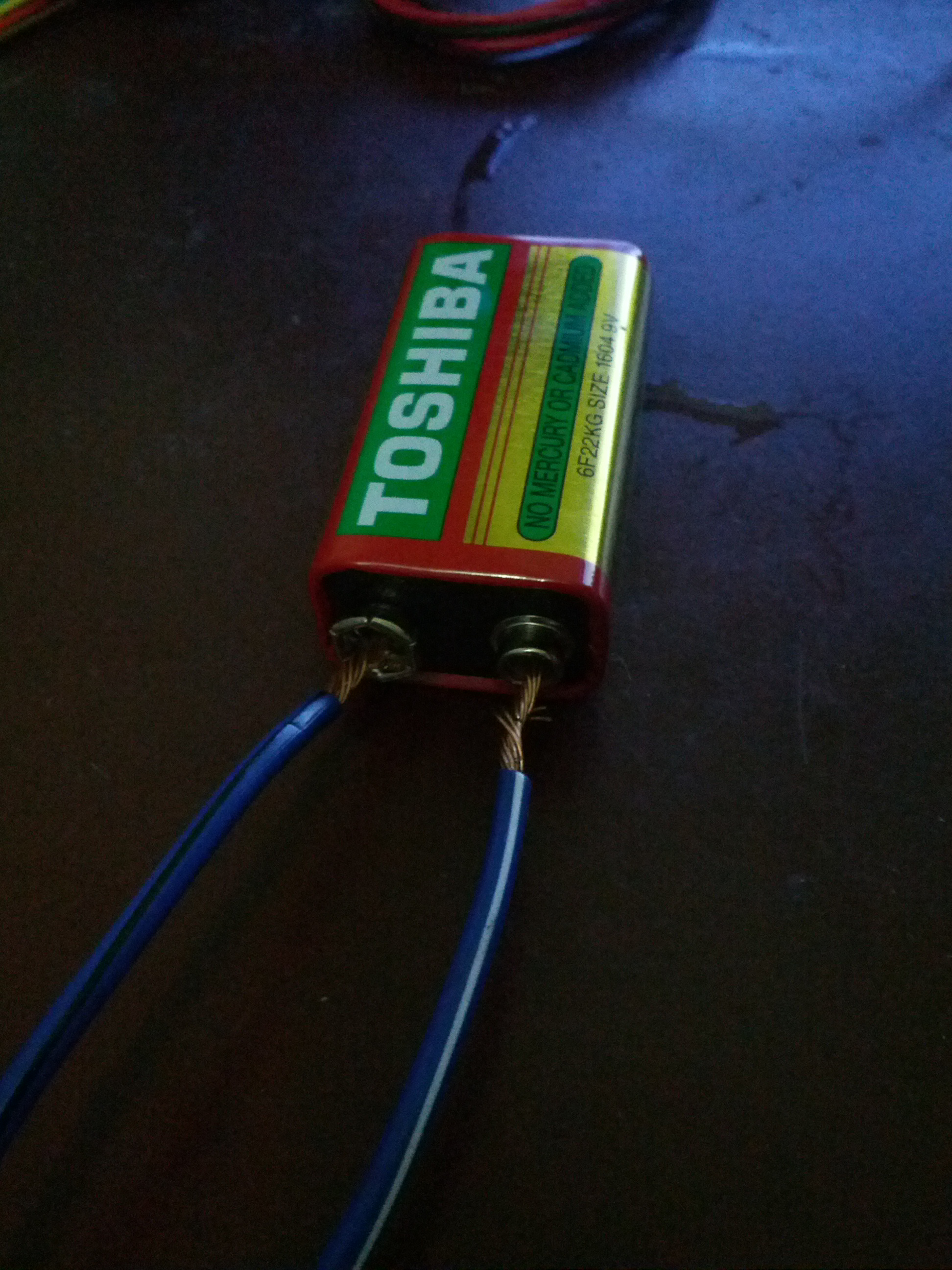
Guys so im running into a problem
I tested the pump at the car shop, he just plugged it into this huge var battery and I heard the motor of the pump running
But now when I hook up my 9V nothing happens
This is how I just hooked it up just to test it http://d24w6bsrhbeh9d.cloudfront.net/photo/axNA0mn_700b.jpg
And no , its from a 12V car (I assume this since it's written 12V on the pump)
But the folks above said that shouldn't be a problem
I now connected the two batteries in series (totaling 18V) and still nothing happens
You can see a few sparks flying when touching the pumps wires though
take a car battery ! borrow one for the day. or get a power supply for a 9 or 12 volt output.
if the motor spins backwards, just swap the leads around.
a car battery charger will output enough for your demonstration.
as for the 9v, PARALLEL ! not series.
9 volts will work, but it seems you need lots more power.
an old power supply from a computer will give you both 5v and 12 v.
a wall wart for a large device could work.
