I need some help in electronics, I am totally new into this so any help would be highly appreciated.
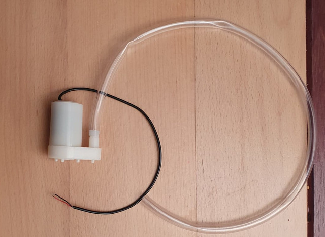
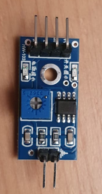
A few months ago I have ordered an Automatic watering water pump with a moisture sensor for learning purpose and to play with my Arduino Uno later. Unfortunately, my electronics knowledge is limited, and therefore I have trouble with setting up the wires. Actually I don't know what am doing .
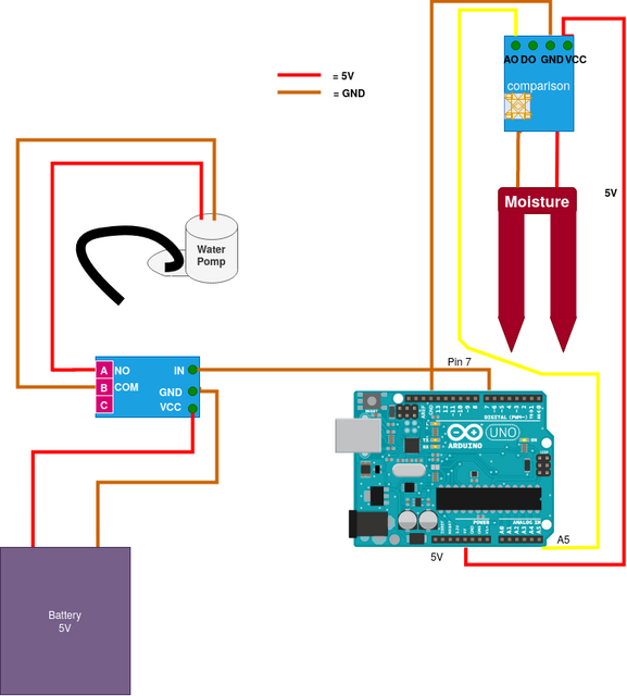
I have made a drawing of the components and the wires and how far I understood the instructions on product page of the webshop. However, I strongly doubt if this the way to go so that's why I ask for your help. I have tried to make the drawing clear with numbers so that we can communicate well on this topic.
Please add the pictures to your post and then add the link inside the post so the image is shown. People here do not like to go offsite looking for files.
There is a "How to post" section at the beginning of each sub forum for other good tips on how to help people to help you.
You can modify the original post. This will also show you the magical tool bar.
Klaus_K:
Please add the pictures to your post and then add the link inside the post so the image is shown. People here do not like to go offsite looking for files.
I tried that but it doesn't work till I realize you have to add the link too. Thanks for the advice.
I hope my post makes more sense now.
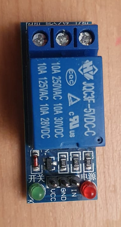
It is definitely not wired right. What do you think the relay is doing there? It is called a circuit for a reason and best to try an understand it that way. Pixies from one side of the battery want to move to the other side and you have to create a route for them to do that. Pixies do work along that route. If you attach a wire to positive of battery and direct to negative (don’t) you have made a circuit and the pixies will run so fast they burn the wire!
Look at you relay and think about what it is there to do? It is supposed to act as a switch on a circuit, controlled by a signal from your arduino. One side is the arduino side, the other the switches circuit side. These should be separate. The arduino side says IN (signal for switch) GND (common ground or negative) and VCC (power in to activate switch). The other side has 3 screw terminals which probably say NO (normally open) which is normally the side you connect your device positive to, NC (normally closed) normally you leave this unwired and COM (common) where you attach the power source for your switched circuit.
Connections
In: a pin on your arduino which is normally set as an output and set high. Drive low to activate relay.
GND: common ground the negative side of battery which arduino gnd is connected to
VCC: positive supply for coil of relay (will be displayed on relay volts)
NO: pos wire of pump
COM: pos supply to pump I.e battery
NC: blank
When you add a signal from the arduino you power the relays coil which disconnects a switch joining COM to NC and reconnects it to NO. So the normally closed circuit becomes open (circuit is broken, no power flows) and the NO circuit becomes closed (circuit is closed and power flows). The NC side of the circuit is normally ignored because it works to power something all the time until you activate the relay whereas the NO side is off all the time until you activate the relay.
So now you have an arduino powered switch which opens or closes the positive wire connected from the battery to COM. You now connect the NO (which is off but will turn on if the arduino activates the relay) to the positive of your pump. Now when your relay is active the positive of the battery is connected to the positive of your pump. To complete the pump circuit you need to connect the negative of the pump back to the battery. Now your pump is pumping.
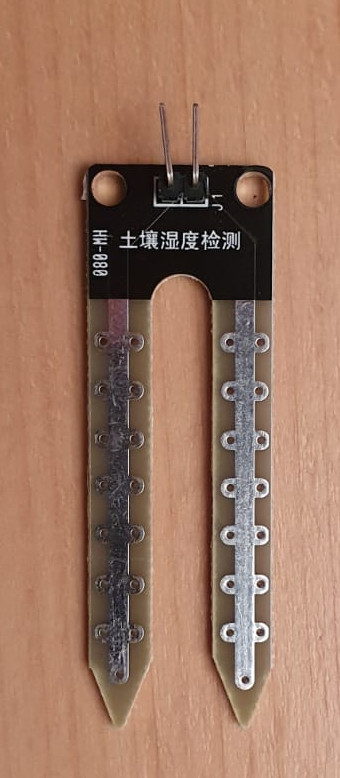
The final device is the sensor and it is a completely separate circuit
The sensor needs power so read its specs and connect the VCC to positive of a suitable source and the GND to negative. Now the sensor will output its signal on the DO or DA pins depending if you want a digital (on off) or analog (variable reading) signal. I suspect you want analog so you can analyse on the arduino. You connect this to an input pin on the arduino and the. Write some code to analyse the signal and activate your relay pin by driving it to low. There will be sample code online.
Hopefully now everything is wired to its own circuit providing the pixies a route to and from the battery through the devices that they will make work.
Caveats: read the data sheets. I am not an expert just an interested beginner so my understanding may be corrected by those more knowledgeable. Good luck
Thank you Pmagowan, this is helpful, let me draw it out on the drawing map I have and repost the map again when I am done so that we both can see if we understood each other.
Like I said in my first post,
I am totally new into this
and I do not have any electronic background but I am very eager to learn
Wiring up the components like this is ok for learning & understanding basic circuits. But not for watering plants. You will quickly find that it floods them! So you will need that Arduino.
The reason the Arduino is needed is that timing is important when watering plants. The soil soaks up the water quite slowly, and you need to water for a few seconds, then wait for several minutes before taking another reading and maybe watering for a few more seconds. There's no point taking readings while the pump is running because the reading will lag several minutes behind.
JCA34F:
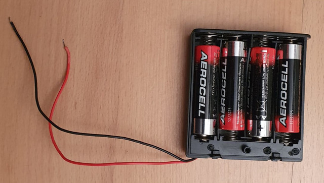
Are those alkaline batteries (1.5 volt)? What's going to happen to your 5 volt components if you put 6 volts on them?
Yes, probably I need to use an resistance. But if I use Arduino Uno in this story then I have 5V onboard because of the Arduino itself so actually I don't need the batteries.
But as you will find out you do need the battery. The arduino is unable to drive the pump and power a number of devices. The arduino can output 5V but only at ~500mA. You should only really use the arduino for its internal logic and ability switch things off and on through a relay or transistor so that the current is not being supplied by the arduino. This is precisely why you have the relay to separate the low power arduino (thinking) circuit from the high power (doing stuff) circuit.
pmagowan:
But as you will find out you do need the battery. The arduino is unable to drive the pump and power a number of devices. The arduino can output 5V but only at ~500mA. You should only really use the arduino for its internal logic and ability switch things off and on through a relay or transistor so that the current is not being supplied by the arduino. This is precisely why you have the relay to separate the low power arduino (thinking) circuit from the high power (doing stuff) circuit.
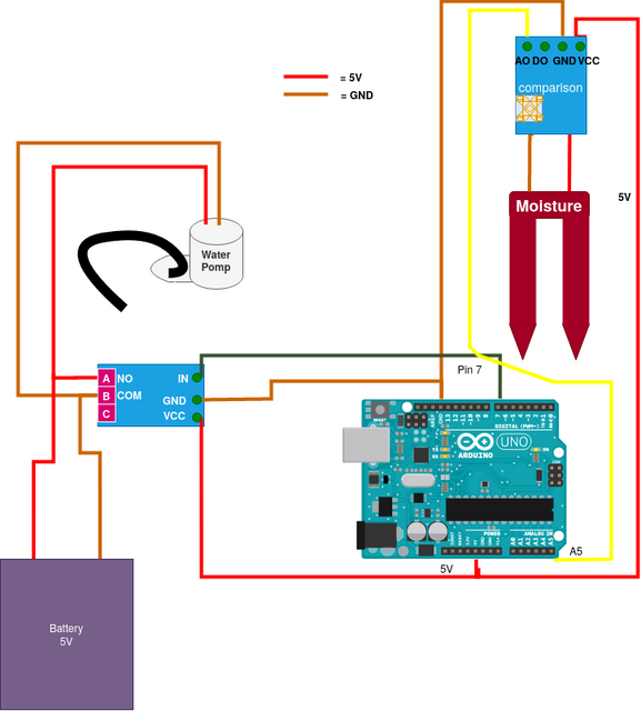
Some aspects are better, the sensor is connected correctly to the arduino, and the arduino is connected to the relay correctly, but the relay is not correctly connected to the pump. Remember, the contacts of the relay are like a switch. You can use them to connect or disconnect power to the pump. Right now, no power can reach the pump.
There is no power source now, how will you power the circuit? Remember that the 5V output from the Arduino cannot run both the relay and the pump, and maybe not the pump at all.
No. Look at the wires you have drawn between the battery, relay and pump. Follow them with your eyes, as the current will flow. See that the pump will run as soon as you connect those wires. When the relay is activated, the relay will short + to -, causing the pump to stop, and the wires and batteries to get hot, until they run flat.
ruliezz:
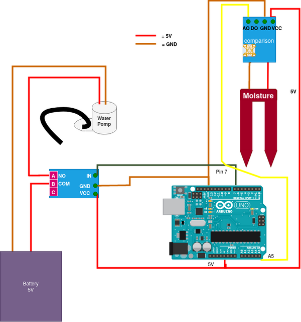
So if its not like the picture in post #12 or in #15 then I don't understand what it should be. Maybe you can use my picture to draw what you mean.
Connect the battery to the pump with two wires, nothing else. This will make the pump run continuously.
Then cut the red wire. The pump will stop and you have two blank end. You connect one end to A and the other to B of the relay. Now the relay will "repair" the cut in the wire when activated.