Hi, luc08
Hi, it's my first project with an Arduino board.
This is a very challenging "first project"! To understand 9DOF sensor data fusing, I strongly recommend this discussion.
As mentioned in reply #1, this call won't work with your sensor, because the axes of the sensors are not aligned consistently.
filter.update(gx,gy,gz,ax,ay,az,mx,my,mz);
The Madgwick/Mahony code assumes that the first sensor axis in the function call points to magnetic North, but the illustration in the sensor data sheet assumes that the accelerometer Y axis and the gyro Y (R) axis point toward magnetic North, while the magnetometer Y axis is assumed to point magnetic South.
Furthermore, the magnetometer axes are defined in a left handed coordinate system, which must be corrected.
If you want to stick with this data sheet convention, then I believe that the filter call should be as follows, and you have to hold the sensor module as illustrated, with accel Z up and Y North. Unfortunately, I don't have one of those sensors to test it.
filter.update(gy,gx,-gz,ay,ax,-az,-my,mx,-mz);
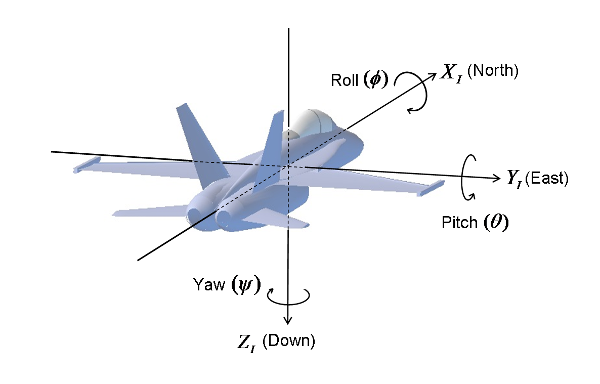
Notes: The Euler angles that you derive from the quaternion produced by the filter won't necessarily have the correct sign, because (1) there is no universal convention on what constitutes a positive rotation (and the mathematical definition of a positive rotation angle used in trigonometry does not agree with conventional navigation) and (2) there are around a dozen ways to define Euler angles. So feel free to change the sign of yaw, pitch or roll to suit yourself.
Finally, this is not necessary, as the filter uses normalized accelerometer and magnetometer readings (vector magnitude =1.0)
I converted ... mg to g and miligauss to µT.