Bare Atmega32u4 bootloader via atmega2560 as ISP

Hi folks

For an apprentice and his project, we try to flash an Atmega32U4 as almost completely bare chip.
Of course, directly from mouser, the Chip is not recognised/programmable via USB directly.
At least the Bootloader is missing i understand (Correct?)...

So, we tried to flash the bootloader via "Arduino as ISP" thru a Mega2560.
The fact that i am posting here, indicates, this flash was unsuccessful... :wink:

So, what did we do?

  • Connected Arduino2560 and gotten COM11 assigned.
  • Arduino Mega2560 sucessfully flashed with ArduinoISP-Sketch on COM11
  • We added the 10uF-Cap on the Arduino2560 between Reset and GND

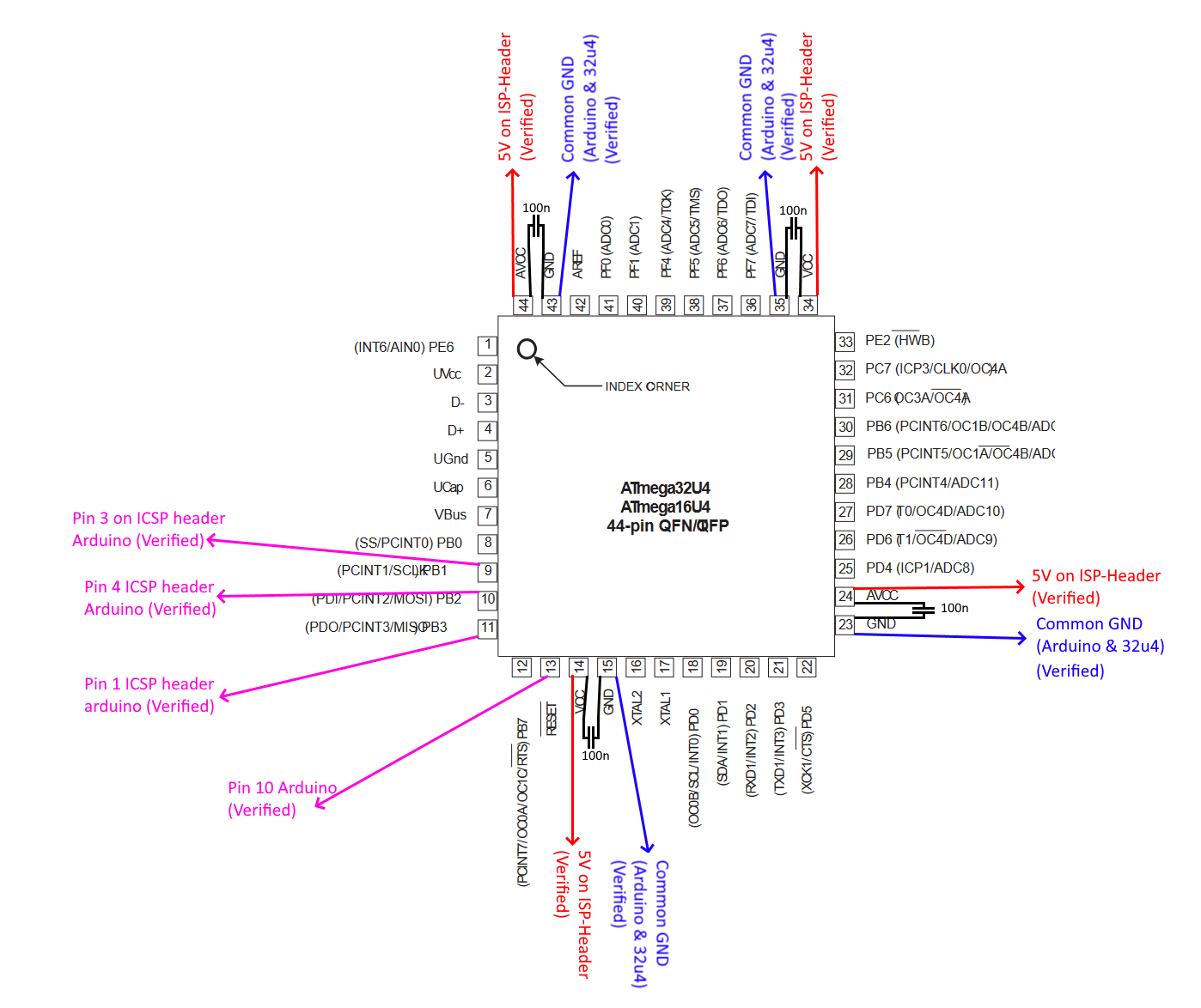
We also added 100nF on the 32u4 at:

  • Pin 14 VCC --> Pin 15 GND
  • Pin 34 VCC --> PIN 35 GND

Connected “bare” Atmega32u4 chip to Arduino2560:

  • Arduino 2560 VCC on ICSP-header (Pin 2) --> 32u4 VCC (CPU Pin 14)
  • Arduino 2560 GND on ICSP-header (Pin 6) --> 32u4 GND (CPU Pin 15)
  • Arduino2560 MOSI on ICSP-header (Pin 4) --> 32u4 MOSI (CPU Pin 10)
  • Arduino2560 MISO on ICSP-header (Pin 1) --> 32u4 MISO (CPU Pin 11)
  • Arduino2560 SCK on ICSP-header (Pin 3) --> 32u4 SCLK (CPU Pin 9)
  • Arduino2560 DIO10 --> 32u4 /RESET (CPU Pin 13)

In Arduino IDE, we then set:

  • Board = “Arduino Leonardo” (As it also uses 32u4) but we also tried “Sparkfun Pro Micro” which also has 32u4 (Both gave the same results further below)
  • COM = COM11 (The Arduino2560 is there with the ArduinoISP-Sketch on it)
  • Programmer = Arduino as ISP

When we click “Burn Bootloader”, we get:

     "C:\Users\ruth2\AppData\Local\Arduino15\packages\arduino\tools\avrdude\6.3.0-arduino17/bin/avrdude" "-CC:\Users\ruth2\AppData\Local\Arduino15\packages\arduino\tools\avrdude\6.3.0-arduino17/etc/avrdude.conf" -v -patmega32u4 -cstk500v1 -PCOM11 -b19200 -e -Ulock:w:0x3F:m -Uefuse:w:0xcb:m -Uhfuse:w:0xd8:m -Ulfuse:w:0xff:m


     avrdude: Version 6.3-20190619
     Copyright (c) 2000-2005 Brian Dean, http://www.bdmicro.com/
     Copyright (c) 2007-2014 Joerg Wunsch

     System wide configuration file is "C:\Users\ruth2\AppData\Local\Arduino15\packages\arduino\tools\avrdude\6.3.0-arduino17/etc/avrdude.conf"

     Using Port                    : COM11
     Using Programmer              : stk500v1
     Overriding Baud Rate          : 19200
     AVR Part                      : ATmega32U4
     Chip Erase delay              : 9000 us
     PAGEL                         : PD7
     BS2                           : PA0
     RESET disposition             : dedicated
     RETRY pulse                   : SCK
     serial program mode           : yes
     parallel program mode         : yes
     Timeout                       : 200
     StabDelay                     : 100
     CmdexeDelay                   : 25
     SyncLoops                     : 32
     ByteDelay                     : 0
     PollIndex                     : 3
     PollValue                     : 0x53
     Memory Detail                 :

                              Block Poll               Page                       Polled
       Memory Type Mode Delay Size  Indx Paged  Size   Size #Pages MinW  MaxW   ReadBack
       ----------- ---- ----- ----- ---- ------ ------ ---- ------ ----- ----- ---------
       eeprom        65    20     4    0 no       1024    4      0  9000  9000 0x00 0x00
       flash         65     6   128    0 yes     32768  128    256  4500  4500 0x00 0x00
       lfuse          0     0     0    0 no          1    0      0  9000  9000 0x00 0x00
       hfuse          0     0     0    0 no          1    0      0  9000  9000 0x00 0x00
       efuse          0     0     0    0 no          1    0      0  9000  9000 0x00 0x00
       lock           0     0     0    0 no          1    0      0  9000  9000 0x00 0x00
       calibration    0     0     0    0 no          1    0      0     0     0 0x00 0x00
       signature      0     0     0    0 no          3    0      0     0     0 0x00 0x00

     Programmer Type : STK500
     Description     : Atmel STK500 Version 1.x firmware
     Hardware Version: 2
     Firmware Version: 1.18
     Topcard         : Unknown
     Vtarget         : 0.0 V
     Varef           : 0.0 V
     Oscillator      : Off
     SCK period      : 0.1 us


     avrdude: AVR device initialized and ready to accept instructions


     Reading | ################################################## | 100% 0.02s


     avrdude: Device signature = 0x000000 (retrying)


     Reading | ################################################## | 100% 0.02s


     avrdude: Device signature = 0x000000 (retrying)


     Reading | ################################################## | 100% 0.02s


     avrdude: Device signature = 0x000000

     avrdude: Yikes!  Invalid device signature.
     Double check connections and try again, or use -F to override
     this check.


     avrdude done.  Thank you.


     Failed chip erase: uploading error: exit status 1

When we download AVRdude separately and use
avrdude -p m32u4 -c avrisp -b 19200 -e -F -P COM11

the result is:

Device signature = 00 00 00 (retrying)
Device signature = 00 00 00
Error: invalid device signature
Warning: expected signature for ATmega32U4 is 1E 95 87
Avrdude done.  Thank you.

So... I checked 3x and resoldered everything twice... All okay.
Have checked for shorts: nothing

To the picture:

  • The 32u4 is on a doublesided sticky tape.
  • The white USB cable is not plugged in as this will be used AFTER we flashed the bootloader to use direct USB-Flashing (As i understand the Bootloader is needed for this?).
  • The unlabeled wire in white is the Reset of the 32u4 which is connected to Pin10 of the Arduino2560.

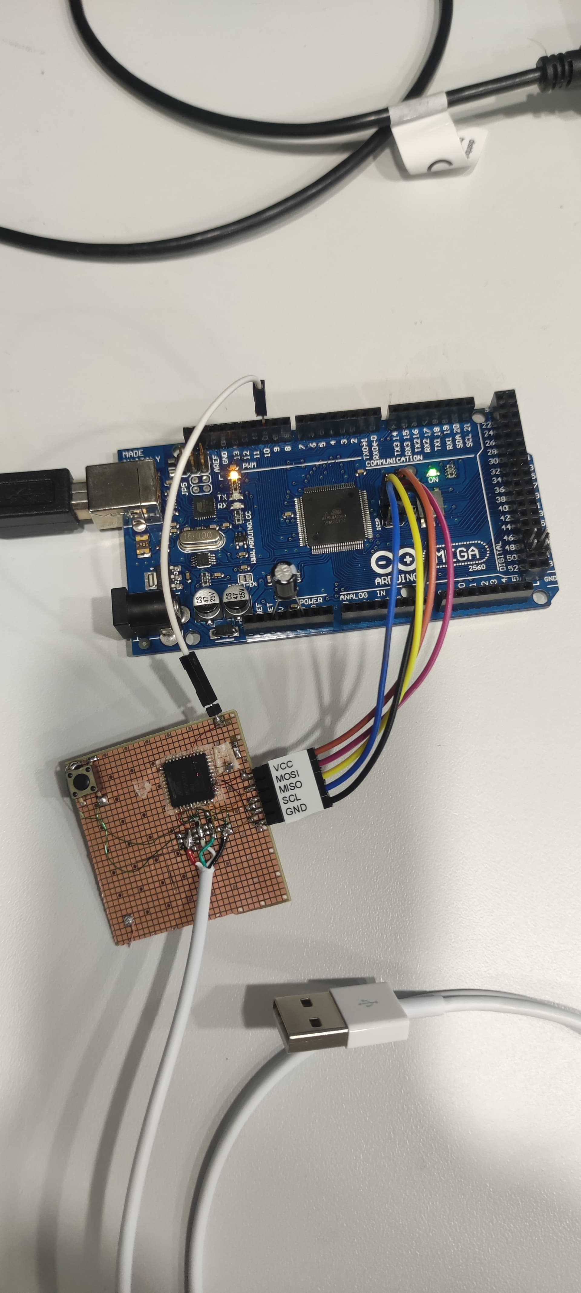
And no: When we connect the white USB of 32u4, nothing is recognized really... no unknown device or even a refresh in the device manager...

When i take the fuse-stuff from the verbose and adapt according the help of AVRdude manpage, i get

C:\work\AVRDUDE>avrdude -v -patmega32u4 -cavrisp -PCOM11 -b19200 -F -e -Ulock:w:0x3F:m -Uefuse:w:0xcb:m -Uhfuse:w:0xd8:m -Ulfuse:w:0xff:m
Avrdude version 8.0
Copyright see https://github.com/avrdudes/avrdude/blob/main/AUTHORS

System wide configuration file is C:\work\AVRDUDE\avrdude.conf

Using port            : COM11
Using programmer      : avrisp
Setting baud rate     : 19200
AVR part              : ATmega32U4
Programming modes     : SPM, ISP, HVPP, JTAG
Programmer type       : STK500
Description           : Serial Atmel AVR ISP using STK500
HW Version            : 2
FW Version            : 1.18
Topcard               : Unknown
SCK period            : 0.0 us
XTAL frequency        : 7.372800 MHz

AVR device initialized and ready to accept instructions
Device signature = 00 00 00 (retrying)
Device signature = 00 00 00
Error: invalid device signature
Warning: expected signature for ATmega32U4 is 1E 95 87
Erased chip

Processing -U lock:w:0x3F:m
Reading 1 byte for lock from input file 0x3F
in 1 section [0, 0]
Writing 1 byte (0x3F) to lock *** failed
Error: unable to write lock (rc = -1)

Avrdude done.  Thank you.

C:\work\AVRDUDE>

the 7.4MHz seem to be the internal clock as the external is/would be 16MHz...
But it looks like it can communicate with the 32u4 but getting signature = bogus...
Or at least read from the 32u4, but cannot seem to write the fuses...
Hm!

So... The main problem seems to be that the signature is = 000000 but for the best of me, i cannot figure out what else needs to be done or done differently to get the bootloader flashed...

The solutions above are the output of many other Forum-threads and solutions... Sadly they dont seem to help here (Like the 10uF on ISP Reset)...

After now many hours, we are at a loss for further ideas.... Please, Hivemind, we beg for ideas and support....

We ordered new chips. I Hope we just had a bad IC, but i am doubtful as it is from Mouser...

Any ideas or Inputs on what could be tried otherwhise?

The Exam-work for their final-Projekt in their apprenticeship involving this just started and time could become an issue.... Please... Ideas? Comment? Anything....

Schematics....

I will deliver Schematics tomorrow as today i am working externally.

But it will be a graphical representation of the info i already posted in first post:

Arduino 2560 VCC on ICSP-header (Pin 2) --> 32u4 VCC (CPU Pin 14)
Arduino 2560 GND on ICSP-header (Pin 6) --> 32u4 GND (CPU Pin 15)
Arduino2560 MOSI on ICSP-header (Pin 4) --> 32u4 MOSI (CPU Pin 10)
Arduino2560 MISO on ICSP-header (Pin 1) --> 32u4 MISO (CPU Pin 11)
Arduino2560 SCK on ICSP-header (Pin 3) --> 32u4 SCLK (CPU Pin 9)
Arduino2560 DIO10 --> 32u4 /RESET (CPU Pin 13)

Maybe a stupid question, but is it necessary to connect the supply (5V) to more than just one VCC-Pin of the 32u4? Is it required to connect 5V to ALL VCC? Like Pin14 AND Pin34? Maybe even to AVCC (Pins 24 & 44)?
GND only on Pin15 enough or is it also Required on 23, 35, 43?

I saw in another post the mention of Pin33 (/HWB) to be connected to GND... Needed?

I assume, Pullup on /Reset of 32u4 is not needed as it is connected to Pin10 of the Mega2560 and the sketch pulls it up/sets high correctly...

ALL AVCC pins MUST be connected to +5
ALL VCC pins MUST be connected to +5
ALL ground pins MUST be connected to Ground

Bypass caps on all VCC pins.

2 Likes

Quite some time ago I built a UV lightbox with the timer control based on an Atmega32U4. I programmed it using an UNO at that stage running the standard ArduinoISP sketch.

I had no problems burning the bootloader or sketch. I later just uploaded the sketch via ISP to eliminate the bootloader and the time it wasted when starting.

I have attached the schematic for that unit, which still operates perfectly, showing all the power and ground connections I used. Hope it helps.

1 Like

Okay... So i will re-try and connect ALL those pins. I assumed (Probably wrongly) they are connected internally... Ahwell... :sweat_smile:

Why the AVCC also need +5V? Arent they for A/D-Conversion and thus (in my understanding) not used in Flashing via MISO/MOSI?
Of course i will hook them up to 5V as suggested by you two. I am just curious why the AVCC are needed in this scenario...

Actually not sure why but for any AVR device datasheet I've read, they always say they must be connected for serial programming and must also be connected whether you use the ADC or not.

True. I just checked the Datasheet of 32u4 (https://ww1.microchip.com/downloads/en/devicedoc/atmel-7766-8-bit-avr-atmega16u4-32u4_datasheet.pdf) to confirm it was used for A/D-Conversion.

  • The AVCC is the supply of the A/D-Conversion
  • And it needs (According to the datasheet for that pin) to be connected to VCC if no A/D-Conversion is in use and be connected to VCC thru a Lowpass filter if A/D-Conversion is in use...

The only hint on why it is needed for for Serial prog (And by this i assume you mean USB?) is found in Figure 21-1: The AVCC seems to power the "PLL & Div/2" block which gives the USB-Interface its clock... No AVCC --> No Clock on USB-Interface --> No USB-Communication --> No USB-Flash.
However, we are here with MISO/MOSI and an own clock (SCK), so this shouldnt be the issue i think.

Figure 28-1 also shows the use of AVCC on 5V but this is for Parallel programming. Also not what we do here with MISO/MOSI...
Hm!

Probably the solution lies in Figure 28-10 and its subtext:
Serial Programming with SCK, PDO and PDI which IS what we try to do: MOSI/MISO and SCK + Reset....
And this clearly shows the connection to VCC on Pin for AVCC. Subtext (Notes 2) on this Pin tells:

VCC - 0.3V < AVCC < VCC + 0.3V, however, AVCC should always be within 1.8 - 5.5V

I think it is this which blocks our efforts to flash...
Ha! I am SOOOOO Curious now for tomorrow! :grinning:

Edit:
For the curious, an excerpt of the datasheet:

2.2.17 AVCC
AVCC is the supply voltage pin (input) for all the A/D Converter channels. If the ADC is not used, it should be
externally connected to V CC . If the ADC is used, it should be connected to VCC through a low-pass filter

and

24.1
The ADC has a separate analog supply voltage pin, AVCC . AV CC must not differ more than ± 0.3V from V CC . See
the paragraph “ADC Noise Canceler” on page 305 on how to connect this pin.

No, AVRs witout USB also require it for serial programming.

Correct.
I wrote this post as i dug my way thru the Datasheet.... Not the only hint in retrospect but the first.. :wink:
Chapter 28.8 "Serial Programming Pin Mapping" is holding the answer that it is needed as written. Sadly, the datasheet is very shy in terms on WHY it is needed... Havent found it yet at least :smiley:

You won't

Hahahaha!
Sad! A curious mind with a question longs for an answer...
I always go like "There is for SURE a logical reason for this... It HAS to be explained somewhere WHY it is how it is." and then i am sad if no such answer is given by the Datasheet.... :sweat_smile: Ahwell...

I have never measured connectivity between the Vcc pins so I wouldn't know, but I can imagine it complicates internals of an MCU if there would be only one power entry. Just look at the fleet of power stages and entries for a modern CPU.

0.1 uF bypass capacitor is de facto, I see @Willem43 used one for all Vcc pins including AVcc, but you can't go wrong with one cap per pin.

True.

The fact that it is stated that it must be connected to 5V whether you use the ADC or not was enough explaination for me.

1 Like

Yes of course thats enough and i didnt see it last week... i never looked at A/D-Pins for flashing :smiley: Ahwell...

Thanks to ledsyn for that link!

Aside from that, they should for full operation of the chip (all ports/pins), to prevent floating pin issues on the AVCC side, to prevent noise on the digital side. There are issues where leaving the AVCC side unpowered causes parasitic power draw and can destablize the internal clock, or can prevent stable startup

Makes total sense. My inner curious child is satisfied :slight_smile:

Will test this tomorrow afternoon and report back if the connection of ALL VCC and GND + ALL AVCC helped. (Honestly i have the feeling thats the culprit)
Till tomorrow: Thanks for those questions, inputs and comments! Highly appreciated! :star_struck:

1 Like

Not to me. Just a bunch of gobbledygook
What's it got to do with the clock?

Yes. That was a long time ago. Right now I would at least use a separate one for the AVCC lines. With all those power lines it gets quite messy adding those caps close to the processor.

Since I made/make my own PCBs, and I cannot do through hole plating, I must leave space around each via to solder a wire through it. That limits the available space close to the processor and eliminate any below it. Things seem to work OK with just the one - better than none.

Okay....

  • I attached ALL VCC and ALL AVCC to the +5V from the Arduino (ICSP-Header).
  • All GND are connected as well (Also thru ICSP-Header).
  • All AVCC & VCC have per Pin their own dedicated 100nF cap directly on the Pin to the GND just one over.
  • Note: /HWB is not grounded, but i tried it with GND there as well... Doesnt change the result...
  • All those connections were optically checked AND beeped thru with a fluke from the 32u4-Pin to the header-Solderjoint of the Arduino. All correctly connecting.
  • I also checked every connection i made on the 32u4 for shorts one pin over. No shorts, all adjacent pins are "open"
  • All AVCC and VCC pins on 32u4 measure a correct 5.00V
  • the 10uF Cap from Reset to GND on the Mega2560 (ISP) is present

With the hardware wired,

  • I flashed again the Arduino Mega2560 with the ArduinoISP-Sketch. Successfully.
  • I changed the type of board to Arduino Leonardo and kept the COM (11)
  • I changed to Programmer "Arduino as ISP"
  • "Burn Bootloader"
    Sadly, the result didnt change from previous attempts:
"C:\Users\ruth2\AppData\Local\Arduino15\packages\arduino\tools\avrdude\6.3.0-arduino17/bin/avrdude" "-CC:\Users\ruth2\AppData\Local\Arduino15\packages\arduino\tools\avrdude\6.3.0-arduino17/etc/avrdude.conf" -v -patmega32u4 -cstk500v1 -PCOM11 -b19200 -e -Ulock:w:0x3F:m -Uefuse:w:0xcb:m -Uhfuse:w:0xd8:m -Ulfuse:w:0xff:m

avrdude: Version 6.3-20190619
         Copyright (c) 2000-2005 Brian Dean, http://www.bdmicro.com/
         Copyright (c) 2007-2014 Joerg Wunsch

         System wide configuration file is "C:\Users\ruth2\AppData\Local\Arduino15\packages\arduino\tools\avrdude\6.3.0-arduino17/etc/avrdude.conf"

         Using Port                    : COM11
         Using Programmer              : stk500v1
         Overriding Baud Rate          : 19200
         AVR Part                      : ATmega32U4
         Chip Erase delay              : 9000 us
         PAGEL                         : PD7
         BS2                           : PA0
         RESET disposition             : dedicated
         RETRY pulse                   : SCK
         serial program mode           : yes
         parallel program mode         : yes
         Timeout                       : 200
         StabDelay                     : 100
         CmdexeDelay                   : 25
         SyncLoops                     : 32
         ByteDelay                     : 0
         PollIndex                     : 3
         PollValue                     : 0x53
         Memory Detail                 :

                                  Block Poll               Page                       Polled
           Memory Type Mode Delay Size  Indx Paged  Size   Size #Pages MinW  MaxW   ReadBack
           ----------- ---- ----- ----- ---- ------ ------ ---- ------ ----- ----- ---------
           eeprom        65    20     4    0 no       1024    4      0  9000  9000 0x00 0x00
           flash         65     6   128    0 yes     32768  128    256  4500  4500 0x00 0x00
           lfuse          0     0     0    0 no          1    0      0  9000  9000 0x00 0x00
           hfuse          0     0     0    0 no          1    0      0  9000  9000 0x00 0x00
           efuse          0     0     0    0 no          1    0      0  9000  9000 0x00 0x00
           lock           0     0     0    0 no          1    0      0  9000  9000 0x00 0x00
           calibration    0     0     0    0 no          1    0      0     0     0 0x00 0x00
           signature      0     0     0    0 no          3    0      0     0     0 0x00 0x00

         Programmer Type : STK500
         Description     : Atmel STK500 Version 1.x firmware
         Hardware Version: 2
         Firmware Version: 1.18
         Topcard         : Unknown
         Vtarget         : 0.0 V
         Varef           : 0.0 V
         Oscillator      : Off
         SCK period      : 0.1 us

avrdude: AVR device initialized and ready to accept instructions

Reading | ################################################## | 100% 0.02s

avrdude: Device signature = 0x000000 (retrying)

Reading | ################################################## | 100% 0.02s

avrdude: Device signature = 0x000000 (retrying)

Reading | ################################################## | 100% 0.03s

avrdude: Device signature = 0x000000
avrdude: Yikes!  Invalid device signature.
         Double check connections and try again, or use -F to override
         this check.


avrdude done.  Thank you.

Failed chip erase: uploading error: exit status 1

I think i will try to scope the lines a bit.... Maybe there is a hint....