This is a very simple project, actually a thermometer with an LED 7 segment display and operated by a push button. It has, however, the special feature that it is runs on a single 1.5 volt AA cell and should have a reasonably long battery life.
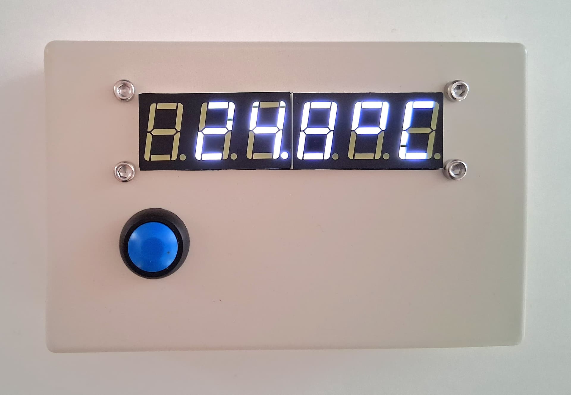
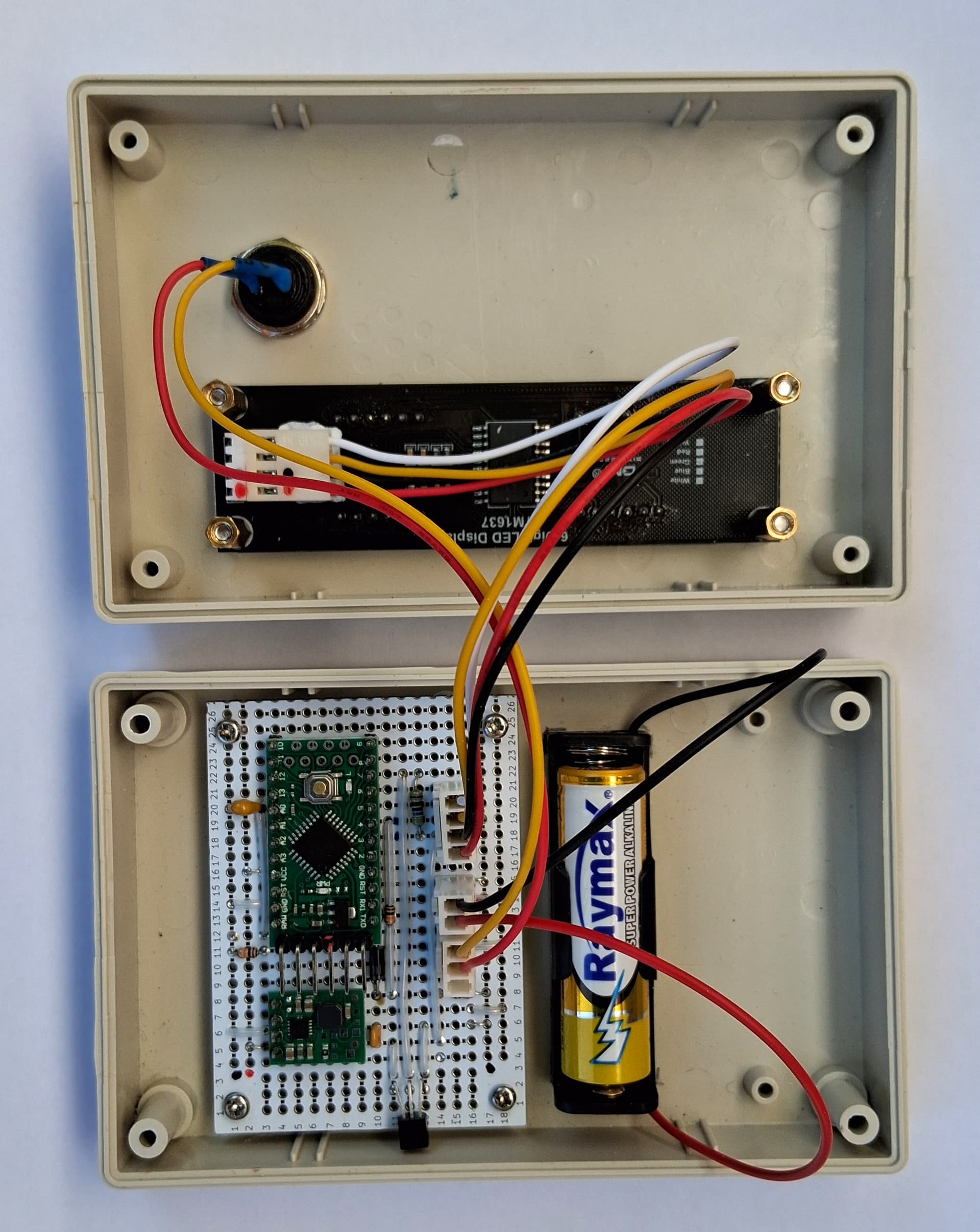
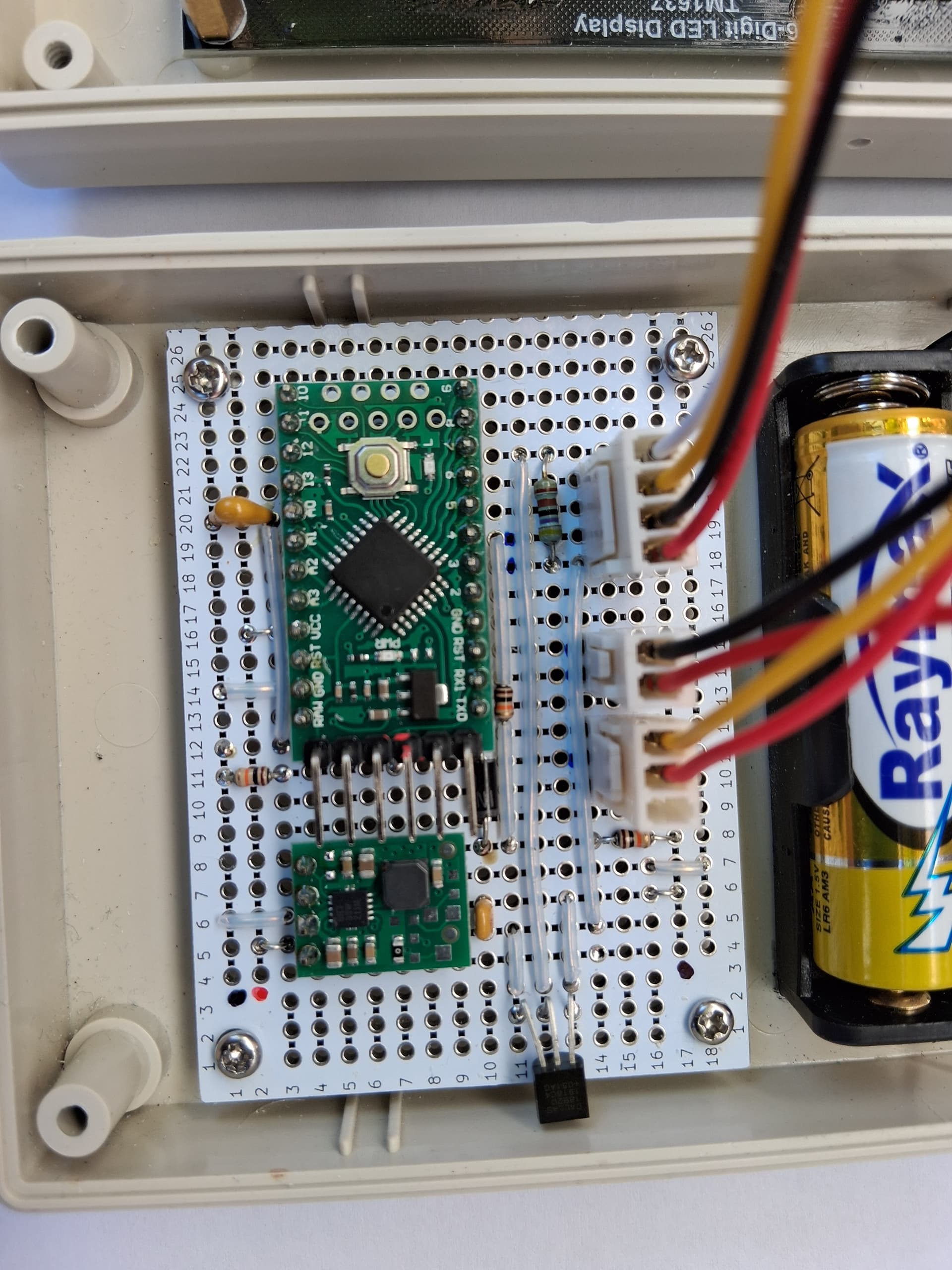
The circuit consists simply of a DS18B20 temperature sensor, a Pololu u1v11f5 boost converter with 5v output, a 6 digit TM1637 display and an LGT8F328P "Pro Mini" clone together with a few miscellaneous components. A button press enables the boost converter which then starts the MCU and latches the boost converter so that the system runs for 5 seconds after the button is released then shuts down automatically.
The choice of MCU is free although the display in this case forced the use of a 5v device. I already has one of the LGT8F328P devices under test so I chose to use that but it is non critical since there is no handling of low level APIs for sleep mode or low power etc. which would normally be board specific. Since the device will be powered on for only a few 5 second sessions per day, no special attention has been given to power savings. The LGT8F328P, although a near clone of the ATMEGA328P, requires its own board package URL to be added to the Arduino IDE.
The display is a 6 digit TM1637 which uses an I2C like interface so requires only four wires to connect it. I used the "Avishorp" library but had to make some hacks to correct the digit order for the specific 6 digit display I used so I have bundled the library with the code below.
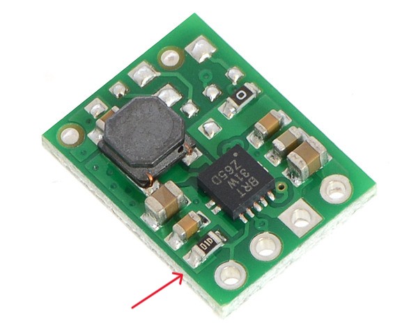
The boost converter, a Pololu U1V11F5, appears not particularly efficient consuming nearly 500mA at 1.5v to power about 60mA at 5 volts however it easy to use because it has an enable pin. In quiescent mode, it appears to have only 2uA leakage. The device as shipped has a 100k pullup resistor on its enable pin so, by default, it is always running when powered. This has to be removed (see red arrow).
I did some experiments also with some cheap Aliexpress boost converters https://www.aliexpress.com/item/1005005624977910.html which work below 1 volt and still deliver 5 volts but these do not have an enable pin so these have to be powered through a high side switch. It is a bit more complicated but these may also be an interesting alternative option because they appear to be more efficient.
I have also a similar but older project with more batteries and no boost converter. There I have misused a tiny AM312 passive infrared sensor as a sort of gesture sensor. The lens is partially obscured to avoid false triggers and a wave of the hand is enough display a temperature reading. The quiescent current is about only 15uA so the battery life should still be reasonable, however these have to be powered at min. 3 volts. I have now seen that it is possible to get PIR sensors which operate down to 1 volt e.g. https://www.zilog.com/docs/zmotion/PS0405.pdf so I may retrofit one in my latest project to replace the push button.
Anyway, the schematic and code are here for anyone who may wish to duplicate the project or otherwise finds some of the details interesting.
Schematic
schematic_latch_temperature.pdf (98.0 KB)
Code
TM1637_DS18B20_LGT_V0_03.ino (5.2 KB)
Code bundled with libraries
TM1637_DS18B20_LGT_V0_03.zip (28.0 KB)