If you don't learn the reasons why and why not, you get: why is this getting hot, why is this not turning on, it worked for a moment etc.
I recommend asking questions here and you will get the help you need. There are some basic characteristics we recommend you to look at when selecting components.
There use to be a link "ABC Arduino" or something like that where you could down load a PDF of typical circuits for the Arduino. I recommend hunting it down if it is still available.
See? That's where I like to live. Halfway between knowing everything and knowing nothing.
If there was a noob list of components, with their engineering add-on descriptions, then it would be much more useful to hobbyists than someone saying "use this one" without the "and here's why" added.
I am capable of looking up a component if I know it's basic function. I found a list of NTE logic level transistors and understood enough of what they were saying but I don't like NTE. I don't know why but I don't.
Graphs don't seem to help. Stating the maximum watts of wasted energy does.
If I found one with a max throughput of 17A @ 100V with a 60W max wasted energy, would that be a good one? I don't plan on 100V and I don't plan on 17A. So, in my thought process if I'm only using 10% of the maximum capability of the transistor then I should be around 6W of loss? I could live with that.

Let's see what you've got.
Attached is a diagram for connecting that dude up.
The "load" could be a motor or LED/s + resistor.
+V could be +5 or "Vin". You work that out.
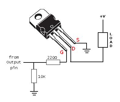
Bittsen, if you use a mosfet, please make a new picture with 'G', 'S', 'D'.
A n-channel mosfet is a low-side switch. It has the 'S' (source) connected to ground.
You are using a BJT image instead of N channel MOS fet IRL540.
If you are driving a incandescent lamp you do not need a fly back diode.
Use fly back diodes on DC components with a coil.
see this is what I mean.
Edit, see:
I will reply in a bit. There's a three year old that's begging for my attention.
OK, new labels (I hope this is correct now).
I won't be using this, right away, for anything with a DC coil but I want to build a "go-to" thing for my future projects and I may, in the future, need a flyback diode.

Yes, but...
Yes, but that's missing the low-value resistor like I showed in my example.
It's a real good idea.
Did you try it?
Crap!
Strike that.
You have +V and Gnd to the transistor wrong.
Why do I bother?
Wiring diagram is still not correct.
Want to use N-channel as a switch to connect "bottom" of Light to Gnd.
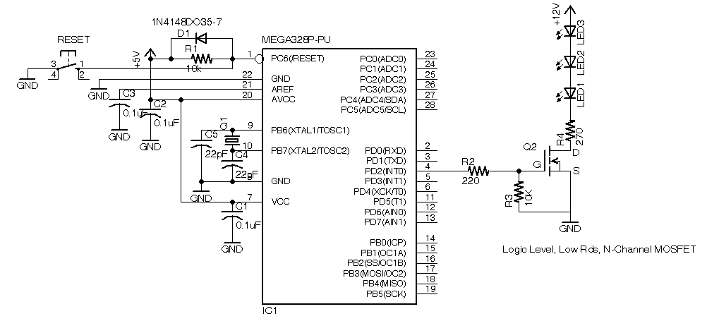
Low value resistor prevents too overcurrent into MOSFET gate capacitance.
Large value resistor keeps MOSFET off during reset state when IO pins are floating.
I haven't tried anything yet. THis is all still theory because I don't have the correct transistor in my possession yet.
In your example, however, you show to be switching the ground. My application won't be able to do this as my applications are going to be mostly automotive.
As most know, automotive is a passive ground system where the entire body of the car is the ground. There's no easy way to put the switch on the negative side so most switching goes on the positive side.
In your example the gate appears to be activated from a negative source, is that correct? If so then adding a resistor from the gate to ground seems like it would trigger some activity in the transistor.
Or am I seeing it wrong?
I do see the benefit of a drain resistor on the gate though. It would assure a true zero if it's important that the gate stays zero in an "off" situation.
This is exactly why I'm posting.
Telling me I have something wrong doesn't help. Telling me how to fix it would help.
Do transistors not trigger with a positive? Or is positive not going to flow through a resistor?
What's the deal?
I don't know why people, like you, feel it's necessary for a hobbyist to learn engineering to be able to build a simple circuit.
This is why. . .
So you want "high side" switching vs "low side".
N-channel is not good for that.
You need P-channel to go between 12V and the "top" of the load - and that requires an extra transistor because the Arduino can't switch 12V on/off.
I posted that diagram earlier in this topic. A pullup resistor to 12V keeps the P-channel off, a high into the NPN base turns the NPN on, which pulls the P-channel gate low to turn it on.
You need a copy of my book - it covers the basics like this.
No, the transistor turns on when the Gate goes positive.
You cannot source current from an N channel MOSFET.
When did we start talking about cars?
Bittsen:
Ha,
I have been playing with a p40NF0 all morning. By playing with it I mean I've been picking it up and trying to figure out if it would be right.
I think I have a few of these laying around.
Bittsen:
THis is all still theory because I don't have the correct transistor in my possession yet.
Come again???
See Reply #5 again, covered this before you got off into the Darlington discussion.
Here's your drawing rendered rightwise (attached).

Yes, for N-channel. See Reply #5 for P-channel & high-side switch.
The transistor I was "playing with" is different than the one I put in my drawing.
Your drawing makes complete sense if I'm switching the negative.
I have been looking for a solution for, primarily, car applications the whole time. ALl of my drawings have been to switch the positive side. It appears there was a misunderstanding wbout that and all the suggestions have been centered around switching the negative side.
It's frustrating because whenever I put a Pchannel somewhere someone says I need a Nchannel. Then I get a handful of advice that's completely the opposite of whatever I just learned.
Then some people come in and call me a fool (not in so many words).
If I wanted to switch the negative then it's not an issue. But everything I'm working on is built around a positive 5V digital output from the arduino.
I will look again at post #5