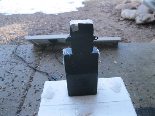
Here is some code that reads the BME680 and sends the data to the MQTT Broker for distrubitioon.
/*
   Project, use solar cells to generate power
   2/2/2020

*/
#include <WiFi.h>
#include <PubSubClient.h>
#include "certs.h"
#include "sdkconfig.h"
#include "esp_system.h"
#include "freertos/FreeRTOS.h"
#include "freertos/task.h"
#include "freertos/timers.h"
#include "freertos/event_groups.h"
//#include "esp_sleep.h"
#include <SPI.h>
#include <Adafruit_Sensor.h>
#include "Adafruit_BME680.h"
////
#define evtDoMQTTwd          ( 1 << 1 )
EventGroupHandle_t eg; // variable for the event group handle
////
WiFiClient wifiClient;
PubSubClient MQTTclient(mqtt_server, mqtt_port, wifiClient);
//////
Adafruit_BME680 bme( GPIO_NUM_5 );
///
/*
   This semaphore is used to stop or prevent a publish from happening during client.loop()
*/
SemaphoreHandle_t sema_MQTT_KeepAlive;
SemaphoreHandle_t sema_mqttOK; // protects the int mqttOK
////
int mqttOK = 0; // stores a count value that is used to cause an esp reset
////
/*
 * A single subject has been scribed to, the mqtt broker sends out "OK" messages if the client receives an OK message the mqttOK value is set back to zero
 */
void IRAM_ATTR mqttCallback(char* topic, byte * payload, unsigned int length)
{
  xSemaphoreTake( sema_mqttOK, portMAX_DELAY );
  mqttOK = 0;
  xSemaphoreGive( sema_mqttOK );
} // void mqttCallback(char* topic, byte* payload, unsigned int length)
////
// interrupt service routine for WiFi events put into IRAM
void IRAM_ATTR WiFiEvent(WiFiEvent_t event)
{
  switch (event) {
    case SYSTEM_EVENT_STA_CONNECTED:
      break;
    case SYSTEM_EVENT_STA_DISCONNECTED:
      log_i("Disconnected from WiFi access point");
      break;
    case SYSTEM_EVENT_AP_STADISCONNECTED:
      log_i("WiFi client disconnected");
      break;
    default: break;
  }
} // void IRAM_ATTR WiFiEvent(WiFiEvent_t event)
////
////
void setup()
{
  sema_mqttOK = xSemaphoreCreateBinary();
  xSemaphoreGive( sema_mqttOK );
  eg = xEventGroupCreate(); // get an event group handle
  xTaskCreatePinnedToCore( MQTTkeepalive, "MQTTkeepalive", 20000, NULL, 5, NULL, 1 );
  xTaskCreatePinnedToCore( fDoBME, "fDoBME", 20000, NULL, 3, NULL, 1 ); // assigned to core
  xTaskCreatePinnedToCore( fmqttWatchDog, "fmqttWatchDog", 3000, NULL, 3, NULL, 1 ); // assign all to core 1
} //void setup()
////
////
void fmqttWatchDog( void * paramater )
{
  int maxNonMQTTresponse = 20;
  for (;;)
  {
    xEventGroupWaitBits (eg, evtDoMQTTwd, pdTRUE, pdTRUE, portMAX_DELAY );
    xSemaphoreTake( sema_mqttOK, portMAX_DELAY );
    mqttOK++;
    xSemaphoreGive( sema_mqttOK );
    if ( mqttOK >= maxNonMQTTresponse )
    {
      ESP.restart();
    }
  }
  vTaskDelete( NULL );
} //void fmqttWatchDog( void * paramater )
////
void connectToMQTT()
{
  MQTTclient.setKeepAlive( 90 ); // needs be made before connecting
  // create client ID from mac address
  byte mac[5];
  WiFi.macAddress(mac); // get mac address
  String clientID = String(mac[0]) + String(mac[4]) ; // use mac address to create clientID
  while ( !MQTTclient.connected() )
  {
    // boolean connect(const char* id, const char* user, const char* pass, const char* willTopic, uint8_t willQos, boolean willRetain, const char* willMessage);
    MQTTclient.connect( clientID.c_str(), mqtt_username, mqtt_password, NULL , 1, true, NULL );
    vTaskDelay( 250 );
  }
  MQTTclient.setCallback( mqttCallback );
  MQTTclient.subscribe( topicOK );
  log_i("MQTT Connected");
} // void connectToMQTT()
////
void fDoBME ( void *pvParameters )
{
  if (!bme.begin()) {
    log_i("Could not find a valid BME680 sensor, check wiring!");
    while (1);
  }
  // Set up oversampling and filter initialization
  bme.setTemperatureOversampling(BME680_OS_8X);
  bme.setHumidityOversampling(BME680_OS_2X);
  bme.setPressureOversampling(BME680_OS_4X);
  bme.setIIRFilterSize(BME680_FILTER_SIZE_3);
  bme.setGasHeater(320, 150); // 320*C for 150 ms
  float fTemperature = 0.0f;
  float fPressure = 0.0f;
  float fHumidity = 0.0f;
  uint32_t iGasResistance = 0;
  TickType_t DelayTime = 1000 * 30;
  //wait for a mqtt connection
  while ( !MQTTclient.connected() )
  {
    vTaskDelay( 250 );
  }
  for ( ;; )
  {
    fTemperature = bme.readTemperature();
    fTemperature = (fTemperature * 1.8f) + 32.0f; // (Celsius x 1.8) + 32
    fPressure = bme.readPressure();
    fPressure = fPressure / 133.3223684f; //converts to mmHg
    fHumidity = bme.readHumidity();
    iGasResistance = bme.readGas();
    xSemaphoreTake( sema_MQTT_KeepAlive, portMAX_DELAY ); // whiles MQTTlient.loop() is running no other mqtt operations should be in process
    log_i( "Temperature %f C, Pressure %f mmHg, Humidity %f, gasResistance %d", fTemperature, fPressure, fHumidity, iGasResistance );
    MQTTclient.publish( topicOutsideTemp, String(fTemperature).c_str() );
    vTaskDelay( 5 ); // gives the Raspberry Pi 4 time to receive the message and process
    MQTTclient.publish( topicOutsideHumidity, String(fHumidity).c_str() );
    vTaskDelay( 5 ); // no delay and RPi is still processing previous message
    MQTTclient.publish( topicOutsideGasResistance, String(iGasResistance).c_str() );
    vTaskDelay( 5 );
    MQTTclient.publish( topicOutsidePressure, String(fPressure).c_str() );
    vTaskDelay( 5 );
    xSemaphoreGive( sema_MQTT_KeepAlive );
    xEventGroupSetBits( eg, evtDoMQTTwd );
    vTaskDelay( DelayTime );
  } // for loop
  vTaskDelete ( NULL );
} // void fDoBME ( void *pvParameters )
////
/*
    Important to not set vTaskDelay to less then 10. Errors begin to develop with the MQTT and network connection.
    makes the initial wifi/mqtt connection and works to keeps those connections open.
*/
void MQTTkeepalive( void *pvParameters )
{
  sema_MQTT_KeepAlive   = xSemaphoreCreateBinary();
  xSemaphoreGive( sema_MQTT_KeepAlive ); // found keep alive can mess with a publish, stop keep alive during publish
  // setting must be set before a mqtt connection is made
  MQTTclient.setKeepAlive( 90 ); // setting keep alive to 90 seconds makes for a very reliable connection, must be set before the 1st connection is made.
  for (;;)
  {
    //check for a is-connected and if the WiFi 'thinks' its connected, found checking on both is more realible than just a single check
    if ( (wifiClient.connected()) && (WiFi.status() == WL_CONNECTED) )
    {
      xSemaphoreTake( sema_MQTT_KeepAlive, portMAX_DELAY ); // whiles MQTTlient.loop() is running no other mqtt operations should be in process
      MQTTclient.loop();
      xSemaphoreGive( sema_MQTT_KeepAlive );
    }
    else {
      log_i( "MQTT keep alive found MQTT status %s WiFi status %s", String(wifiClient.connected()), String(WiFi.status()) );
      if ( !(wifiClient.connected()) || !(WiFi.status() == WL_CONNECTED) )
      {
        connectToWiFi();
      }
      connectToMQTT();
    }
    vTaskDelay( 250 ); //task runs approx every 250 mS
  }
  vTaskDelete ( NULL );
}
////
void connectToWiFi()
{
  int TryCount = 0;
  //log_i( "connect to wifi" );
  while ( WiFi.status() != WL_CONNECTED )
  {
    TryCount++;
    WiFi.disconnect();
    WiFi.begin( SSID, PASSWORD );
    vTaskDelay( 4000 );
    if ( TryCount == 10 )
    {
      ESP.restart();
    }
  }
  WiFi.onEvent( WiFiEvent );
} // void connectToWiFi()
////
void loop() {}
////


