Salutations. I am a complete electronics beginner and just bought myself the nice starter kit. This question is probably completely ridiculous, but I can't seem to make any sense of it.
I've hooked up a photo resistor followed by a 1k resistor to ground and a connection to A0 on the Arduino board to read the voltage. I can see that it seems to work as intended; when I shine a light right at the sensor, I get just under 5V, and when in darkness, it reports close to 0V. Perfect!
But, when I switch out the 1k resistor to a 10k resistor, as indicated in the project book, I still get the same values on A0. I was expecting to see a drop in the values since I added a stronger resistor to my circuit. Why do I read the same values on A0 with either the 1k or 10k resistor connected to the ground? As far as I understand from the project book so far, adding a stronger resistor should lower the current across the whole circuit, but I am apparently very confused about something here. I am thankful for any pointers or good terms to Google!
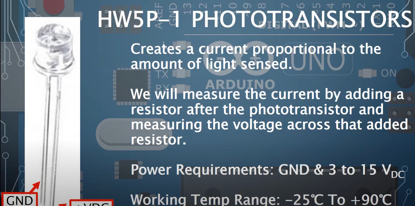
No....what you show is a photo transistor.
Try it with the photo transistor emitter to ground and the collector to A0 with collector through the resistor to positive rail.
Then do a Google search on how npn transistor works.
Thank you all for taking the time to guide a novice like me.
Part of the confusion, apart from me being totally inept, may be due to the fact that the Project Book refers to the devices as "photoresistors". However, after going through my box several times, I concluded that I do not have any devices like those depicted.
I don't have those in my kit. After googling and looking at some video tutorials, I noticed that people were using these instead, so I assume the part may have been updated since the project book was put together:
I have those, and I do get the expected readouts on A0, i.e., almost 5V at full brightness and 0V in darkness. I just don't understand why going from a 1K to a 10K resistor to ground after the transistor does not affect the values I receive on A0.
I am going to buy a multimeter tomorrow to poke and prod a little bit more. That would probably help me understand some of the basic concepts.
Because when there is no light, no current flows through the transistor, so A0 is effectively grounded (0 v)... the resistor is effectively a pull-down resistor.
When you shine light on the transistor it is likely switching to fully open (very low resistance, compared to 10k or 1k) so you now have ~5v at A0.
Did you try shining the light away from the detector (not directly at it), then moving the beam slowly toward the detector while watching the ADC value (0 ~ 1023)?