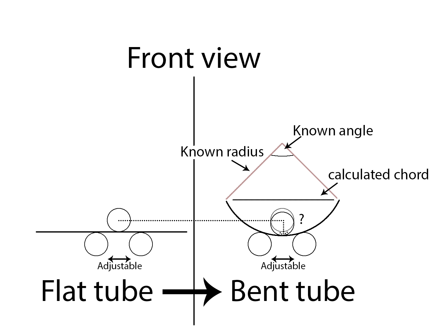
The way this works is the top roller will be pushed down after which the tube is rolled through to create a curvature. Then the top roller is pushed further to create a bigger curvature.
On the one I'm using I can adjust the horizontal spacing between the two bottom rollers.
As you can imagine it takes guesswork to get the desired curvature.
With a known length of tubing, is there a way to calculate how far I have to push the top roller to get a certain curvature for a specified circle radius?
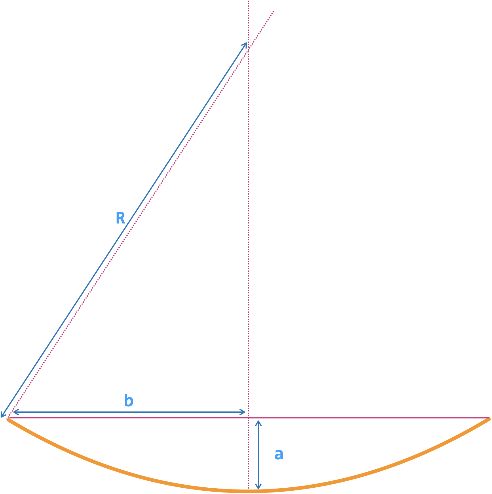
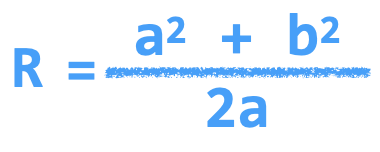
The easy way I would imagine is just get the radius of the circle describing a corner where the arc length is the length of the tube and then calculate the chord.
Then use a string as the chord distance and start bending until I can connect the two ends of the tube with the string without any force.
However I was just wondering if there might be a way to calculate the curvature using the distance between the points where the rollers meet the tube, or any other method for that matter.
The chord calculation would work just fine I imagine, just trying to get some other insights.
Math, trigometry is needed. The end result will use a lot of small steps, from straight to ready bended. Step size depends on the material being bent and the available forces.
Not exatctly an Arduino question.
That's why I posted it in the mechanics part, but maybe I'm missing something since this is the first time posting in the updated forums.
Math, trigometry is needed
could you please elaborate because you seem to have an idea of how it would be calculated (I'm not seeing it), but atm your answer isn't really helping out with my issue.
And don’t forget the tube will have some “ spring “ in it , meaning you’ll need to bend further than you think, also there will be slight compression of the tube ( it won’t stay completely round)
It's great that helpers replies.
I have a master degree in electronics. Being retired I've got myself a little shop with mill, lathe, saw etc.
Your question calls for answers from a master degree machinist. Doing calculations in an Arduino is easy but which formula, what math, should be used? I think that no theory in the world would work all the way. Lots of testing, tuning etc. is needed.
Regarding the springback:
Exactly, did some test bends with some pipes I had laying around and noticed this like you mentioned.
I've done some lookup and it seems there are some formulas for this depending on the material (don't quote me on it however, just did a quick lookup some time ago.)
Heating up some materials also mitigates this to some extent.
As for the compression, I agree.
I've done some tests and watched plenty of videos and this system just isn't suited for round tubing.
Square tubing on the other hand would be better, although like you said it will still have some pinching going on, so I'll add some sacrificial length which can be cut off after reaching the desired curvature.
You are going to need to take the diameter of the tube into account when doing the calculation.
I was thinking this as well, I'll have to experiment a little to see what works and what doesn't.
At first glance I would think, If using square tubing, it doesn't really matter since the top part of the tube will always remain parallel to the bottom, and thus have the same curvature (be it that the top part describes a slightly bigger circle than the bottom one, but I feel this is negligible)
Congratulations, but I feel we're missing the point here?
Like you just mentioned:
which formula, what math, should be used?
... is exactly what I'm after, hence my question.
But your replies, although appreciated, are not really of much help.
With your statement regarding
I think that no theory in the world would work all the way. Lots of testing, tuning etc. is needed.
Let's agree to disagree, again no disrespect intended.
Lots of stuff is based on theory and I prefer to initially study the theory instead of testing without any starting point.
And the diameter of the two side rollers, and the yield strain of the metal the pipe is made from. It may be simpler just to do some measurements and make a calibration chart.
And the diameter of the two side rollers, and the yield strain of the metal the pipe is made from. It may be simpler just to do some measurements and make a calibration chart.
After a quick lookup, I understand it the yield strain is basically the 'spring' we were talking about earlier, right?
That's a bit too far for calculating and like you mentioned a calibration chart will be necessary.
I think the answer from J-M-L Jackson is a good starting point for my calculation so I'm at least within the area of where I want the curve to be.
I think the basic equations will do the job and give the correct characteristics , but you’ll need to add material property dependant fiddle factors into those equations to get the results you want .
Having a Masters , the maths should be easy , so I’ll leave that you ....
Yield strain is the strain at which the material starts to deform permanently - before you
reach that it is still in the elastic zone and will spring back to the original shape - thus the
yield strain is one of the fiddle factors you'll need.
There are loads of good resources out there about material properties like this, but translating
this to your geometry is likely to be a complicated part