Best way to identify a pressed button in a set of buttons?

My use case is:
A garage with 3 rollerdoors, one per bay.
One light per bay.
There are four vertical pillars encapsulating the openings (rollerdoors).
I use a box with 4 momentary switches on each pillar between the rollerdoors.

That is: two boxes with 4 buttons each. One for light one for rollerdoor on the left and one for light and one for rollerdoor on the right.

One button box is connected via Cat6 cable to the Arduino, using only 3 wires (of eight).

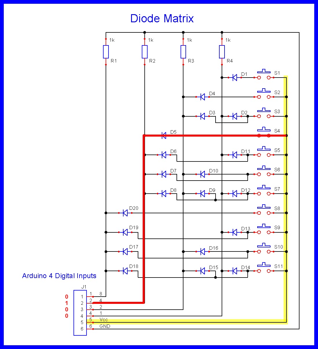
My initial solution was five 10k resistors in series on Vcc to ground, with each button connected between the resistors, like so:

    The diagram
    R1..R5 = 10 kOhm
    sw1..sw4 all momentary push buttons

    Vcc ----         ------ Analog in
           |         |
          |R|        |
          |1|        |
           |___sw1___|
           |         |
          |R|        |
          |2|        |
           |___sw2___|
           |         |
          |R|        |
          |3|        |
           |___sw3___|
           |         |
          |R|        |
          |4|        |
           |___sw4___|
           |
          |R|
          |5|
           |
    Ground_|

I then use code to firgure out which button is being pressed:

/*!
 * ---------------------------------------------|-------------------------------
 * Translate switch id per set (1..4) to consecutive numbers (1..n) across all
 * switch sets (groups)
 * @param button_voltage is the meassured analog input value
 * @param button_group is the switch set
 * @return the button id of the pressed switch
 * ---------------------------------------------|-------------------------------
 */
uint8_t which_button_has_been_pressed(uint16_t button_voltage, uint8_t button_group)
{
    uint8_t button_pressed = 0;

    //  off   on   switch (order from closer to farther from V in)
    // 1018  840   1
    // 1018  673   2
    // 1018  497   3
    // 1014  291   4

    if (button_voltage < 890 && button_voltage > 790)
    {
        // ~840
        switch (button_group)
        {
            case 1:
                button_pressed = 1;
            break;

            case 2:
                button_pressed = 5;
            break;

            case 3:
                button_pressed = 9;
            break;
        }

    }
    else if (button_voltage < 730 && button_voltage > 620)
    {
        // ~673
        switch (button_group)
        {
            case 1:
                button_pressed = 2;
            break;

            case 2:
                button_pressed = 6;
            break;

            case 3:
                button_pressed = 10;
            break;
        }
    }
    else if (button_voltage < 550 && button_voltage > 450)
    {
        // ~497
        switch (button_group)
        {
            case 1:
                button_pressed = 3;
            break;

            case 2:
                button_pressed = 7;
            break;

            case 3:
                button_pressed = 11;
            break;
        }
    }
    else if (button_voltage < 350 && button_voltage > 250)
    {
        // ~291
        switch (button_group)
        {
            case 1:
                button_pressed = 4;
            break;

            case 2:
                button_pressed = 8;
            break;
        }
    }

    return button_pressed;

}   // which_button_has_been_pressed()

This code selects a voltage range to figure out the respective button.

So far so good. This is actually working. :slight_smile:

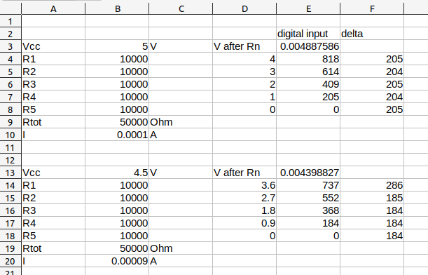
However, I was wondering why the digital values per button are not equally spaced.
It might be clear for most, Vcc may not be the same at each button collection (box) due to difference in cable length, and contact resistances along the way; or the resistors have tolerances, thus have different voltages across them.

My question:

Is there a better way to identify the button that has been pressed, without relying on voltages (ideally without using more pins)?

I could use a voltage reference, which would reduce the range around the ideal value.

As for "(ideally without using more pins)"; I have since replaced the Arduino UNO with a MEGA (as it does more than buttons), and do have more input pins I could use one pin per button.
Plus Vcc and ground would lead to six wires being used ion the Cat6 cable.

The other (self-imposed) constraint is to have a simple solutions, as in less components or even a circuit board.

Any hints appreciated.

I won't address the interval spacing but I will refer you to this Arduino Starter Kit project #7.   Note that your circuit allows the analog input to 'float' when no switch is pressed.

1 Like
  • Why not send back the open/closed state of the switches ?
    :thinking:

At each button box I'd suggest you should have:
A capacitor from Vcc to ground to stabilise the Vcc - say 470uF
Smaller resistors to reduce the effect of EMI
5V 1k = 5mA so you could use 5 * 220 ohm
A pull-up resistor (say 10k) from Analog in to Vcc AND a small capacitor (say 0.1uF) from Analog in to GND.

1 Like

Thanks, I shall add a 10k resistor between ground and analog.

It is not so much a solution for the gap range, but either to keep this range close between button sets, or change the approach to 'reading' a button press.

??? Sorry, I do not understand.

Very helpful, thank you... and will do.


So it seems, there is not real objection to using my V-divider logic?

For example, I thought I could BCD-encode the buttons with a few diodes, thus eliminating voltage fluctuations/jitter, etc. altogether.
However, I would not know how to combine the different digital inputs to make a decimal? --- Maybe voltage divider it is. :slight_smile:

If you could use 4 digital pins then 5 wires would be enough, one per button and GND. You could buy a cable with 5 thin wires.

Maybe it would be a simpler setup, in the code you would just need to read high/low on each pin.
And it would be more robust as the signal levels would be 5V or 0, no calibrations and less chance of problems and maintenance. And pressing more than one button at the same time wouldn't be a problem.
Anyway your setup should work also.

You should move R5 to the other side of SW4; that will prevent the floating of the analogue input without affecting the readings.

Use a Diode matrix.


  • Switch #4 in garage sends 0100 (4) to the Arduino.

Note

  • GND and the resistors can be back with the Arduino.

If you have enough pins on the MEGA I would go for one button = one pin. That will make maintenance and the code easier.

Hello MaxG

Keep it simple and stupid:

Take 2 Arduinos and let them talk to each other via a serial interface.

1 Like

How does a button detect a light?

The middle rollerdoor is detected by 2 buttons? Why?

What does the 4th button in each box do?

Three doors have four pillars. Pillar 1 next to one door; pillar 2 can operate the door to the left and to the right; the same applies to 'switching" the lights. Same arrangement between door two and three; pillar 4 only operates door three.
However, I do not have a box on one outer door, but have one on the other, which also switches two external lights separately. To make sense, button one for the rollerdoor, button 2 or the light in that bay, and three and four for two external lights.
I hope this explains it better.

About the same, I would say. A diagram would be worth 1000 words.

But I think I am getting closer to understanding, please correct me if I got anything wrong. These button boxes are wired, remote controls for the system that controls the doors and lights. The momentary switches don't sense whether the doors are open/closed or if the lights are on/off, only if human fingers are pressing them, which would normally only ever be one switch pressed at a time.

I can't think of any suggestions except those you already have already been given.

I provided one; simply ignore the fact there are multiple boxes (which are all the same, but use a different analog input). It is also irrelevant, if they actuate lights or rollerdoors.
this is about capturing button presses, either via a voltage divider, or something better.

Well, I think, and given I have the pins (and wires), I'll go for direct connection of buttons to digital inputs.

There is a 2-wire solution (further below) = less work to wire up.

Thank you for all your input. :slight_smile:

You could simply use a two-wire circuit, with a unique resistance for each button and a lookup table of thresholds(not explicit values). It works quite well for me. Takes a bit more 'smarts' in the code, which you seemed interested in in your first post, but it sounds like wire-per-button is your chosen route. That gets it done, for sure.

1 Like

Not bad... are you talking about the switches in parallel with different value resistors; like so:

  ------------------------ [Vcc]
  |      |      |      |
 |1|    |2|    |3|    |4| [kOhm]
  |      |      |      |
  |      |      |      |
  \      \      \      \
  |      |      |      |
  ------------------------ [A0]

A0 with a pull down to ground at the controller.


Good spotting my 'rather software' approach.
I am still learning to code, and am moving from C to C++ or should I say, from procedural to OO... just created my first class; a relay class for the relay outputs.

Would this not just be a variation of my ranges in the switch statement?

    if (button_voltage < 890 && button_voltage > 790)

... one reason I asked my initial question. The ranges vary with Vcc changes.
image

Yes, you can do it that way. I dislike 'iffy' ranges, because there's more editing involved in making changes. I simply scan a table, and the index of the first value greater than the value read is the answer. Need to change a value, I change one entry in a table.
I have not found that much variation on the VCC-based conversions on my Nanos. I may just be lucky, or it may be because I specifically do NOT use the Arduino VCC to power other stuff, just the Nano.

You seem to be focused on ADC changes of only a few counts. This is a ten bit ADC, my past experience tells me to never rely on the last two bits(at best).

In fact, in my lookup table and analog read, I specifically reduce the ADC result to 8 bit(after doing a double read, discarding the first), and values in my LUT are all single bytes. It works. What can I say?

Hmm... is this something like:

1 1 1 2 2 2 3 3 3  4  4  4 <- translated or identified button?
0 2 3 4 5 6 7 8 9 10 11 12 <- what is measured*

* measured simplified, could be intervals of 10 or 50...
... or can you give me a hint?