Hello gurus,
I'm having some success reading sensor output from a 12VDC coin hopper as coins get ejected from it. The challenge is that its sensor output is causing my Trinket M0 (running Arduino sketch) to wig out intermittently when receiving signals (fine at all other times), resetting. Aware that this is not an Ardiuno device specifically (can test soon), I have a hunch that the sensor output is throwing too much voltage at the sensor input occasionally.
The coin hopper sensor output is "open collector NPN - active low, maximum sink of 25mA at 35Volt maximum". I have the built-in pull-up resistor enabled when receiving signals in the Trinket.
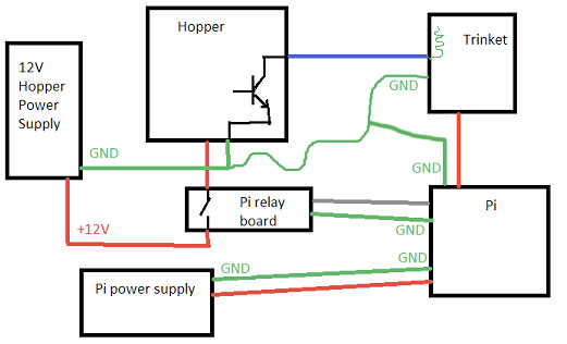
The hopper is powered by a 12VDC power supply connected with a relay. The coin hopper's ground connection goes back to the power outlet while the single sensor wire connects to a digital input pin. I've learned that this may deliver "floating" values which can be unpredictable.
I found somewhere in an ancient IRC chat from 2013 (sorry I lost link) that I may be able to add a ground wire somewhere in-between with a 10kohm resistor and have learned here in my discussion of a possible need for a capacitor. Honestly though, I'm still an electronics newbie and am not sure how I would configure this.
Any ideas on how I would tame the volts? :o
This is going towards a charity project that I'll be happy to share once completed. Thanks in advance for your time and awesomeness!
owntheweb:
I have a hunch that the sensor output is throwing too much voltage at the sensor input occasionally.
The coin hopper sensor output is "open collector NPN - active low,
Any ideas on how I would tame the volts?
There are no volts to tame. Open collector and active low means if the output is low, you get 0V. Otherwise you get the volts you apply to the pin with the pullup, viz 5V.
(At least, that's how I always understood "open collector")
edit: is the coin box thing's ground connected to the Trinket's? (not clear to me.)
If you have only the sensor and not the ground connected between the box and the Trinket, that's like trying to read the voltage on a battery with only one wire from the meter ;). You need both sides, else there's no circuit.
So yeah you need that ground connection between the two....
(The 3.3 vs 5 is neither here nor there: the pin will be pulled to 3.3 by the internal resistor when the coin box is not pulling it low, and it's that low that you should be looking for, hence the term "active low". It will "know" that the 3.3, while not 5, is not low, since it's a 3.3 device in the first place. I forget the numbers but a 3.3 device will see a low as below 1V say, and high as above 2.5 say. (Not the right numbers, illustrative purposes only ) )
owntheweb:
The challenge is that its sensor output is causing my Trinket M0 (running Arduino sketch) to wig out intermittently when receiving signals (fine at all other times), resetting.
You would connect the Hopper output and Hopper 12VDC to the inputs of the 'optocoupler' board and the VCC, Out,GND to the Trinket.
With this you don't need to connect the Hopper 12V to the trinket or its power supply at all, which is an advantage because the motors in those coin hoppers can generate quite a lot of electrical noise.
If you are also turning on and off the hopper from the Trinket, you can use another opto-isolator in the other direction.
Thanks for the excellent feedback. I'm excited about octocouplers and am reading up on it.
Sending coin hopper ground to the Trinket isn't quite making sense to me yet. Current reasoning (feel free to correct): I would expect that the power outlet powering the hopper would need a ground connection going back to the outlet. I'm already using the Trinket's ground connection to connect to a Raspberry Pi pin as it gets a power connection from there as well. So outlet powers coin hopper. Pi powers the Trinket.
As a visual person, let me attempt to draw out the full picture of my current connections for discussion (see attachment).
Let me know if this helps fill in some gaps, and let me know how this might alter what plugs into what.
EDIT:
Thank you for the note about the schottky diode as well. Good reading happening here. Cheap to try as well.
wilfredmedlin:
Perhaps (if and) when you do V2 of the schematic you could also add the pullup resistor to 5V at the Arduino end of the output.
The OP's first post:
The coin hopper sensor output is "open collector NPN - active low, maximum sink of 25mA at 35Volt maximum". I have the built-in pull-up resistor enabled when receiving signals in the Trinket.
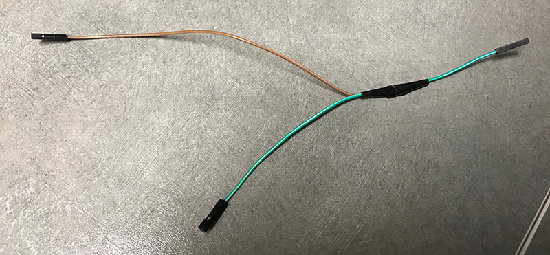
I didn't get a chance to try this out with family happenings just yet (soon!), but I do have a quick question. See attachment. The Trinket has one GND pin. Any issues if I connect as illustrated?
EDIT:
I also have an Arduino UNO in hand now, and will load the sketch there for comparisons today.
Layout doesn't matter much as long as everything is connected to one another. Multiple wires to one pin is fine. If you use a breadboard, just connect it individually to the power rails.
This does start to matter when you have have high currents (several amps), switching motors, and that kind of disturbances. Doesn't seem to be the case here.