I have created a script to control a Star Trek model and simulate weapons. The part that I am referring to is referenced in the sections labeled "Quantum Torpedoes." I apologize, but I've tried to use 2 LEDs to simulate 1 bicolor LED because Tinkercad doesn't have that in their library. I will use 2 bicolor LEDs in the actual model.
Code is working just fine.
My intent was to us a bicolor LED to have it flip between white and red to simulate a launch. What is happening is that the LED seems to have both colors lit at the same time. I'm 100% positive that it's the common cathode. Tinkercad does not have a bicolor LED, but I think I have simulated it here. Resistors are 470 ohm.
For a bicolor led, what would be the proper wiring for it to be powered with a separate power supply triggered by an arduino PWM pin through a N-channel logic level mosfet?
// Notes
// - All time is in milliseconds

// Global Variables and library loads
unsigned long now;    //time from millis()
#include <ezButton.h> // ezButton library
#include <ezOutput.h> // ezOutput library

// Navigation Lights
#define NAV_LED_PIN 12
#define NAV_LED_ON 150
#define NAV_LED_OFF 1000
unsigned long NAV_msLast;  // last time the LED changed state
boolean NAV_ledState;    // current LED state

// Pulse Cannons
const int PC_BUTTON = 10; // The number of the pushbutton pin
const int PC_PIN = 11;  // The number of the LED pin
int PC_blinkF = 250; // How long between flashes
int PC_blinkT = 10;    // How many flashes do you want times 2 5 flashes = 10
ezButton buttonPC(PC_BUTTON); // create ezButton object that attach to pin 13;
ezOutput led(PC_PIN);    // create ezOutput object that attach to pin 9;

// Quantum Torpedoes
#include <ezButton.h> // ezButton library
#define QT_EFFECT_NONE 0
#define QT_EFFECT_BLAST 1
#define QT_EFFECT_FULL 2
#define QT_EFFECT_DIM  3
#define QT_TIME_X 3000 // 300 ms. YOU CAN CHANGE IT
#define QT_TIME_Y 1500  // 100 ms. YOU CAN CHANGE IT
#define QT_TIME_Z 2000 // 100 ms. YOU CAN CHANGE IT
#define QT_BRIGHTNESS_A  150 // YOU CAN CHANGE IT
#define QT_BRIGHTNESS_FULL 255
#define QT_BRIGHTNESS_LOW 0
const int QT_BUTTON  = 9; // the number of the pushbutton pin
const int QT_WHITE = 3;  // the number of the LED pin
const int QT_RED  = 5;  // the number of the LED pin
unsigned long QT_mslast;
unsigned int ledEffectState = QT_EFFECT_NONE;
ezButton buttonQT(QT_BUTTON); // create ezButton object that attach to pin 7;

void setup(void)
{
  Serial.begin(9600);
  pinMode(NAV_LED_PIN, OUTPUT);
  pinMode(QT_WHITE, OUTPUT);
  pinMode(QT_RED, OUTPUT);
  buttonPC.setDebounceTime(50); // set debounce time to 50 milliseconds
  buttonQT.setDebounceTime(50); // set debounce time to 50 milliseconds
}

void loop(void)
{
  // Normal Stuff
  now = millis();
  buttonPC.loop(); // MUST call the button.loop() function in loop()
  buttonQT.loop(); // MUST call the button.loop() function in loop()
  led.loop();  // MUST call the led.loop() function in loop()

  // Navigation Lights
  if (now - NAV_msLast > (NAV_ledState ? NAV_LED_ON : NAV_LED_OFF)) {
    digitalWrite(NAV_LED_PIN, NAV_ledState = !NAV_ledState);
    NAV_msLast = now;
  }

  // Pulse Cannons
  if(buttonPC.isPressed())
  {
    Serial.println("The pulse phaser button is pressed.");
    led.blink(PC_blinkF, PC_blinkF, 0, PC_blinkT); // ON, OFF times. 0 means blink immediately, blink off/on X times
  }

  // Quantum Torpedoes
  if(buttonQT.isPressed()) {
    Serial.println("The quantum torpedo button is pressed.");
    ledEffectState = QT_EFFECT_BLAST;
    QT_mslast = millis();
  }

  long progress;
  long brightness;

  switch(ledEffectState)
  {
    case QT_EFFECT_BLAST:
    progress = millis() - QT_mslast;
    brightness = map(progress, 0, QT_TIME_X, QT_BRIGHTNESS_LOW, QT_BRIGHTNESS_A);

    if(brightness <= QT_BRIGHTNESS_A) {
      analogWrite(QT_RED, brightness);
    } else {
      ledEffectState = QT_EFFECT_FULL;
      QT_mslast = millis();
      analogWrite(QT_RED,  QT_BRIGHTNESS_LOW);  // led is OFF immediately
      analogWrite(QT_WHITE, QT_BRIGHTNESS_FULL); // led is fult bright immediately
    }
    break;

    case QT_EFFECT_FULL:
    progress = millis() - QT_mslast;
    if(progress > QT_TIME_Y)
    {
      ledEffectState = QT_EFFECT_DIM;
      QT_mslast = millis();
      analogWrite(QT_WHITE, QT_BRIGHTNESS_LOW);  // led is OFF immediately
    }
    break;

    case QT_EFFECT_DIM:
    progress = millis() - QT_mslast;
    brightness = map(progress, 0, QT_TIME_Z, QT_BRIGHTNESS_A, QT_BRIGHTNESS_LOW);

    if(brightness >= QT_BRIGHTNESS_LOW)
    analogWrite(QT_RED, brightness);
    else // led is OFF
    ledEffectState = QT_EFFECT_NONE;
    break;

    default:
    digitalWrite(QT_RED , LOW); // turn off LED
    digitalWrite(QT_WHITE, LOW); // turn off LED
  }
}
What sort of bicolor led have you got?
Also check this link ([u]here[/u]). I added an extra 'relay' ------ which I'm not sure if solid-state relay will be able to just short circuit the bicolor diodes to turn them off (when needed). So just ignore the solid-state relay idea if implemented incorrectly or infeasible here. There will certainly be other options and circuits to get all LEDs to turn off (if needed).
And ------ for your breadboard circuit ....... when the left-hand-side transistor is activated, then both of the 'grey' coloured LEDs will light up. And when the right-hand-side transistor is activated, then both of the 'red' coloured LEDs will light up, right?
Also ----- in your circuit, take a look at both grey-coloured LEDs. And also take a look at the associated 470 ohm resistors. Those to resistors are in parallel.
The situation is the same with the pair of 'red-coloured' LEDs.
So for the grey-coloured LEDs ------ the equivalent circuit appears to be 235 ohm (ie. parallel 470 ohm) that drives two paralleled 'grey' LEDs. Same situation for the pair of red LEDs.
So you want both of the grey-LEDs to turn on at the same time, right? And you want both red-LEDs to turn on at the same time, right?
The pic below just traces the current through the grey-coloured LEDs when the left-hand-transistor turns on. The power gets fed from the big purple dot region when the transistor turns on.
Do you want the choices (red, white) or (red, white, off)?
I like to help- it makes me a better programmer.
But I stop reading when I get to a silly Fritzing picture. I speak in schematic.
Fritzing pictures limit how many people will help with your circuit question.
A lot of people notice and also move on when they see someone post replies without answering any questions that have been posted.
Looks to me like both MOSFETS turn all 4 LEDs on, they appear to be all linked together with the black wired connected to the drains.
Hi,
Please draw your circuit, get a pen(cil) and paper then post a picture of it.
I see two pairs of 470R resistors connected in parallel due to how the protoboard is constructed.
As previously said, Fritzy is a picture, not a schematic, drawing your proposed circuit will give you unlimited component symbols.
Tom... 
This allows white/red/off with a two-pin LED and a single Arduino pin.
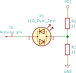
No need to have two parallel resistors and diodes, a single current limiting resistor will do in your circuits, unless you have a very good reason to want two different values for those resistors.
True ...... an arduino digital pin can be set to a sort of tri-state mode by making the pinmode set to 'input' mode. Gives high impedance. But also better check out that information at this link here too - as it just seems there's the life-story thing about ----- how something that should be 'simple' turns out to have extra little fiddly ridiculous stuff associated.
Did you or did you not try simply switching the leds on and off with a switch or jumper wire instead of with code ? (y/n)
First off, let me clarify more accurately what I'm trying to do.
Here is a video example on what I'm trying to replicate. The board is not an arduino, but a vendor in the realm that sells boards. I'm still working on sound, so please disregard.
https://drive.google.com/file/d/1zL7UC3TW6K288FIcT6GeJQ_JAqz_On09/view?usp=sharing
So what it amounts to is 3 steps using pwm and analogwrite. Step 1 - Build up the color red from 0 to a setting that isn't fully on for a duration of time. Step 2 - turn off the red LED and turn on the white LED for a duration of time at full brightness. Step 3 - Turn off the White LED, turn the red LED back at the level it was at the end of Step 1, and slowly dim to 0. This all has to be powered by the external power supply and not the arduino itself, and using a bicolor LED with a common cathode.
If I use separate LEDs for the colors, it works perfectly. Please note, the time has been extended hence why it's slow.
https://drive.google.com/file/d/1Lknv_ripjVziDopjy3Z4LCtX-39KRkvz/view?usp=sharing
When I rewire it up to use the bi-color LED, this is the effect. Both LEDs come on. For this example, it's a blue/amber 5mm bicolor LED. Kinda the same but different.
https://drive.google.com/file/d/1nuxUaUS6J3lxUS_jM_xr6Tf-Dw7c-a2g/view?usp=sharing
As you can see, both colors are on at the same time or so it appears. Here is the circuit diagram on what I'm trying to accomplish.
Thanks for the help all!!!
Well, with the two MOSFET drains connected together, either MOSFET will power ALL the LEDs when conducting. I'm completely baffled about why you did that.
Your attempt at an explanation, is really "backsplaining". Instead of going on about PWM and all that, please just answer the question in reply #3. Because if the answer is (red, white, off), then you have an additional problem with your circuit. For 3 states, you need two digital outputs. So you would need 4 outputs in total and 2 more MOSFETs since you have 2 bicolour LEDs.
It's nice to see a proper schematic but it has the same problem that has already been pointed out several times already.
aarg:
please just answer the question in reply #3
I'll need both red and white on at different points per the script.
I apologize for wasting time and space in the arduino continuum. I just felt I wasn't being very clear.
PerryBebbington:
It's nice to see a proper schematic but it has the same problem that has already been pointed out several times already.
I was asked for a schematic, and tried to produce. Yeah I went a bit overboard, but wanted to avoid confusion on what I'm trying to accomplish.
raschemmel:
Did you or did you not try simply switching the leds on and off with a switch or jumper wire instead of with code ? (y/n)
I have. All LEDs function properly and still have their smoke fuse intact.
aarg:
For 3 states, you need two digital outputs. So you would need 4 outputs in total and 2 more MOSFETs since you have 2 bicolour LEDs.
Won't I still have the problem with the common cathode of the bicolor LED?
Would a diode work in this situation to isolate either mosfet drains?
chipnod2020:
I'll need both red and white on at different points per the script.
I apologize for wasting time and space in the arduino continuum. I just felt I wasn't being very clear.
Amazingly, you still haven't answered the question. Because both red and white on, says nothing about the other states. Please, can you list ALL the desired output states, ONE at a TIME?
Then we can talk intelligently about a proper driving circuit...
How about considering an H-bridge driver? Then you could drive the regular bicolor LED in any which way you want. And even use PWM to change brightness. But noting that ----- for a regular bicolor LED ------ when 1 diode is powered up, the other is becomes unpowered.
Maybe there are other sorts of multi-color LED ----- maybe there is ..... that allows independent control of all colours inside the device. So that all colours can be on at the same time ...... with independent brightness control. Not sure. Such a device would obviously require multiple pins I guess ------ for supply and control functions.


