Hi, I am trying to control a BLDC motor (A2122 930KV) connected to a Simonk 30A ESC using an ESP32. I understand that this motor requires a 5V PWM signal, which is why I use a level shifter to convert the ESP32’s 3.3V GPIO (pin 4) to 5V PWM. However, the motor does not seem to respond. Previously, I tested the motor with an Arduino UNO, and it worked perfectly.
The Code
//ESP32 CODE
#include <ESP32Servo.h>

#define ESC_PIN 4

Servo esc;

void setup() {
  esc.attach(ESC_PIN, 1000, 2000);
}

void loop() {
  esc.writeMicroseconds(1200);
  delay(20);

}
The Schematic

I also tested the output of the ESP32 Code(Listed Above) with the Arduino UNO board(Code Listed Below) to make sure that the ESP32 is outputting a proper PWM Signal, which after testing, it is.
The Schematic Connection Between Esp32 and Arduino UNO

//Receiving End Arduino UNO CODE
const int pwmPin = 2;  // Input from ESP32
unsigned long duration;

void setup() {
  Serial.begin(115200);
  pinMode(pwmPin, INPUT);
}

void loop() {
  // Measure the HIGH pulse duration
  duration = pulseIn(pwmPin, HIGH, 25000); // timeout 25 ms
  Serial.print("PWM width: ");
  Serial.print(duration);
  Serial.println(" us");
  delay(20);
}
The Code for Arduino UNO controlling BLDC motor is this link(lessons/BLDC_Motor/BLDC_Speed_Control.ino at main · un0038998/lessons · GitHub)
I apologize if my post is not up to the standard, as this is my first post on this Forum and I am not familiar with how this Forum works. Thanks
Specs:
Esp32: ESP32-S3 N16R8
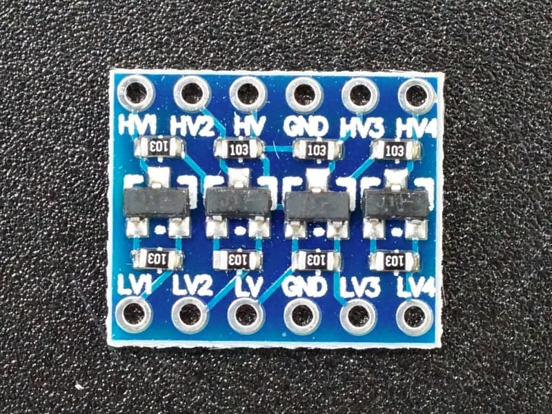
Level Shifter: Bi-Directional Logic Level Converter (4 Channel) 3.3V/5V
Arduino: Arduino UNO board
BLDC: A2122 930KV
ESC: Simonk 30A
Battery: Lipo 3S 5300mAH