Board suggestion to control relays for 12V system, 8 momentary switches to toggle and possibility to use an app to toggle outputs also?
I'm new to all of this but am excited to learn. I am simply looking to use momentary switches to provide output to control a relay, and possible use a phone app to control the outputs as well. Some momentary switches will be multifunctional as to control 2 different outputs cycling the switch. Off - Circuit 1 and 2 On, (PRESS) Circuit 1 Off and Circuit 2 On, (PRESS) Circuit 1 and Circuit 2 Off for example.
I am not sure what board would be best suited or overkill for this task. (Switch Controlling, 8 -12 circuits
Any board having 2 outputs and 8 inputs would do. If the relay coils use the same voltage as the board, powering is simple. Use relay modules, not relays.
Welcome. Any would work but the UNO is the default standard. The Nano is the same thing on a smaller footprint with the additional of two more A/Ds pined out. To do a phone app you will need an external radio module, the ESP devices have the radio on board and will talk to a WiFi without additional hardware. The ESP devices are newer and run on 3V3. Most of the Arduinos are 5V.
I recommend you spend a few days reading the forum, putting together a program document stating what you want it to do and what you need to do it. You should put together a preliminary schematic at this point. Since you are just starting I will suggest you start with a schematic capture program, the frizzing junk does not do a lot for explaining the circuit, just where to put the wires. You can post your schematic and your code if you have started on it.
The IDEs will let you write code and compile it without a board. You could also follow some tutorials showing what or part of what you want to do. You can do this while you are waiting for your copy of the Arduino Cookbook, the best book you can get as a beginner.
Assuming you have a computer the only initial expense will be time then a few Arduino boards, expect to fry at least one and a USB cable. Hint the Arduino boards do not do anything, they just control so if you use a relay you need to get one that has a driver built in.
This particular application is going to be used on a boat / yacht, 12V system to drive relays that will turn on navigation lights, blower motors, courtesy lights etc. All 12 volt stuff. 3 to 10 amp. Intending on switching the relays via ground control.
The relay module I have in mind is from Electronics - Salon, 8 Channel.
Super appreciate the input here. I thank you. I would like to run the board via 12VDC from the systems main power on the boat if that means anything. Prefer not to add a buck converter to bring down to 5V but will take the appropriate reccomendations. Does the Arduino Mega support the 12V input better?
Also the relay control module I was looking to use has 12V Relays, I can get 5V I believe as an option but was looking to trigger the relays / activate them via ground trigger. Would drivers still be needed using a ground trigger / activation as an output?
Again, totally new. I'm sure there's lots to learn! =)
That will eventually fry your Arduino if it works. Use 12V relays, they will still work with the logic output of most Arduinos. They have either a transistor or MOSFET to drive the relay. I would recommend the buck converter just to protect any Arduino. I would set the output to about 8V and power via Vin. Using Vin gives additional decoupling from the power source. You need to consider what happens if the battery gets connected in reverse, the appropriate buck converter would protect you. I do not know your boat but I would expect transients in at least the 50V range. If you use solid state relays I think you will be much happier in the long end as they do not corrode or wear out as fast.
There are many clones available, some have switching power supplies on board and will supply current to accessories, most will not. My background in boats is very weak but I expect the boat electrical will be almost as bad as a car especially if it charges the battery with an alternator. Happy boating!
Since you mention using a phone to control relays I would suggest you first give this a read. There are other wireless solutions but for starters the ESP8266 would be a good choice. The link starts out simple with a single relay and advances to multiple relays. I am guessing something like this is what you are after.
It is yes. I'm trying to avoid using a relay module to control another relay module as well. Most of these relay modules do not handle a lot of amperage. In my case some up to 16 amps required. Even 20 amps.
Maybe something I'm trying to understand still is when you request an output from a GPIO pin, say to LOW to activate a relay, or optocoupler?, what kind of signal is this from the GPIO pin?
Is this not a constant ground to keep the relay energized? Or is that where certain relay modules have certain components on them to hold the relay closed until it receives a HIGH signal??? I have an automotive background in 12 volts but not on the electronic side if you know what I mean, so I'm used to a relay being energized by either 12 volt positive or 12 volt negative and then de-energized when power or ground is removed.
It is a 12 volt relay module that I am looking to use. A 5 volt version is available.
I think I'm trying to understand the output from say an Uno, GPIO pin. I'd like to control it via ground side, I'm used to 12 volt automotive industry where you can apply a ground to a relay or 12 volt positive and it energizes. When you remove ground or remove 12 volt positive, it de-energizes the relay. Does the GPIO output work in that manner or can it? Or does it only tap/pulse a LOW /Ground as output?
If it doesn't hold to ground, how do I achieve that with the relay module that requires raw input? I would need a relay module that has another component on it that would allow it to latch with a pulse signal? Then unlatch when pulsed again?
OK, no problem. Matter of fact if you want to use 12 volt relays no problem, a relay with a 12 volt coil. Matter of fact if you want to use 12 volt automotive relays no problem. You can buy 12 volt automotive relay blocks which include fuses. This is one example.
You can use a logic low or logic high to drive your relays. How much current do you need to handle and are you switching AC or DC current? I assume DC current.
I have some 5 volt and 12 volt relay boards which go active when a logic low is applied and they work fine with the link I gave you.
You can have whatever you want, just well define the project and someone here will offer guidance and suggestions. That includes circuit suggestions to drive your relays of choice. You want wireless remote using your phone?
Incidentally if a relay goes active on a logic high or logic low is simply a matter of the code and I believe they mention that in the link I posted earlier.
Could you better define logic high or logic low? I kind of get the zeros and ones part to the logic high and logic low. Is this a constant output? Is logic low a ground output that would directly drive or operate a regular 12 volt automotive relay or even a 5 volt relay module to switch 12 volt DC devices?
I appreciate your time and input. I could easily purchase a 5 volt relay module with eight channels that would accomplish what I am looking for, here's an example. DIN Rail Mount AC/DC Control DPDT 5Amp Pluggable Power Relay Interface Module (AC/DC 5V, 8 Relay) https://a.co/d/hxW7BZx
Also available as 12V
Literally just want to use standard automotive momentary switches to pulse ground or "low" to a controller whether it be ESP or Arduino and it act as a latching output to hold a relay energized to control a 12 volt DC Load. Then toggle to de-energize the relay.
I could utilize an optocoupler to drive the relay module as well if that better isolates or protects the controller. If I'm understanding that right.
DONGKER Optocoupler Isolation Board,DC 3.3V 5V PNP NPN 8-Channel Signal Converter Opto Voltage Isolation Module https://a.co/d/1Sm3dqW
Yes I am familiar with those relays, you are describing the NC contact. Automotive Relay Guide | 12 Volt Planet Connecting that type of relay coil to the Arduino should fry the Arduino, I expect it to draw a few hundred mA. You need to put a relay driver in your circuit for the 'automotive' relay coil. Those relays switch a lot but also require a lot of coil power. Take a serious look at a solid state relay.
The Electronics - Salon website shows a multitude of 12V, 8 channel relay modules. Please post a datasheet link or the brand name and part number of the one you have.
Sure, we can do that. When you hear terms like logic low or logic high what they mean is a logic low is typically 0.0 volts on a digital out pin. Logic High could be about 3.3 volts or 5.0 volts depending on the module used. So what we do in code is write a digital pin output either High or Low to activate our relay or whatever we have out there on that pin. We use a digitalWrite in out code, that is covered here.
Write a HIGH or a LOW value to a digital pin.
If the pin has been configured as an OUTPUT with pinMode(), its voltage will be set to the corresponding value: 5V (or 3.3V on 3.3V boards) for HIGH, 0V (ground) for LOW.
Next, in your first post you mentioned relays handling 16 to as much as 20 amps. This is why I suggested using quality automotive relays. Tell you right now the relay boards off the boat from China are over rated to begin with. I have a few such boards and while inexpensive I would not even try running 10 amps DC through them. Now if you are comfortable with one of the off the boat relay cards and you are not running 16 to 20 amps for loads, then have at it. Based on your mention of 16 to 20 amps and I assume DC I suggested an automotive relay block. Now if you go that route I or anyone else can make you a nice simple drawing to follow. When we start switching 16 to 20 amps DC you want a quality relay.
It's all coming together! Yes that explanation helped a lot.
So yes, I figured the China boards were going to be questionable quality. Most of my circuits will be 5 amps or less but I did want to consider using the one here listed on Amazon with brand name relays that are replaceable. Electronics-Salon DIN Rail Mount AC/DC 12V Control 8 SPDT 16Amp Pluggable Power Relay Module, G2R-1-E https://a.co/d/hdjwiH0
I have one circuit that might draw 12 amps DC at 12 volts and possibly another as high as 15 amps.
Is there a benefit to using an optocoupler to drive the relay module or is it already built in to this?
And should I consider the 5 volt relay setup to be better fitted to the control board? Or can I power the control board with 12 volts and use a 12 volt relay module? Again, I plan on switching via Logic Low. The momentary switches I was planning to run to the boats 12 volt grounding system.
Those relays will work as long as you are comfortable with them. I have used the 5 volt coil versions in several projects. I will piece together a how to drive them circuit. The Arduino or ESP digital out lines are limited as to how much current they can output. The relay coil current exceeds what the digital out pins can handle. In addition to each relay you would drive the relay coil like this:
The merit to using an opto coupler is isolation. They can be added to the drawing easy enough.
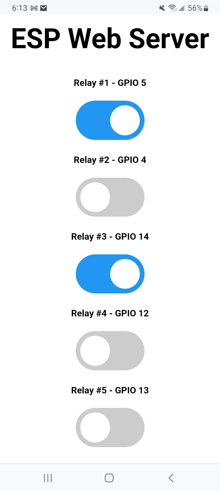
Again, everything I am posting is about remote control of your relays and assumes a network connection. You control the relays through a PC or using a smart phone so it looks like this:
How it shows up on my phone. Relays can be added or subtracted. This is merely an example. Now if you just want to turn relays ON/Off using for example buttons it gets much simpler.
Electronics-Salon DIN Rail Mount AC/DC 12V Control 8 SPDT 16Amp Pluggable Power Relay Module, G2R-1-E https://a.co/d/2r5RbGE
Relay: OMRON G2R-1-E 12V
Channel: 8
Control Signal: Voltage AC 10V~16V, or DC 9V~21V. Current 35mA(at 12V)
Relay Switch Contact Rating: Resistive Load 250VAC/16A 30VDC/16A, Inductive Load: 250VAC/8A.
Omron G2R-1-E industrial power relays, switching current up to 16A at 250VAC (or 30VDC), and easy to replace pluggable relays.
Support AC / DC control signals.
LED indicator for each relay channel , relay coil protection by means of a freewheeling diode.