I am working on a schedule. After a night testing things out on a breadboard, I moved on to a first real prototype (3d printed) and this is what it looks like:
I also made a schematics of it all. This is my very first attempt at using Fritzing -- and in fact my first attempt at drawing a circuit schematics... Please bar with me!
(UPDATED: Sorted out the wires colours and positions as recommended here)
Some notes:
I added the "distribution" block terminals because that's what I did in my project too to have some cable management
Power comes from a 12V 1amp source (a power supply I got from Amazon). It goes into the Vin of the board. I connected the power source to the GND (obviously). I then connected the 5V terminal to another block terminal, and then the other GND of the board. I guess the GND are equivalent -- I could have connected everything to the first GND pin too...
I wish there was a better way of making distribution block terminals... As you can see from the schematics, there probably isn't really a case of a PCB board, since it really is an Arduino connected to a bunch of terminals
My first "used" version will be a Mini with block terminals, so that I will have zero dupoint terminals (except for the sensors, the screen and the keyboard, but I can't help that)
Cable management is better than it looks -- it looks messy because I want the lid to stay open while I program it. The next 3d printed version will have groves for where the cables are. Please note that there are 3 more switches and 3 more pumps going in it, but it will only add cables. I will do that once I have the next 3D printed version with cable management included.
I have some practical questions:
(1) Those terminal blocks are all linked together -- I soldered a wire at the back of them. For the final version, I am thinking of soldering them all together and using Heat Shrink Tubing to hide the soldered part. Is that a good way to go/best practice? Or is there a screw-in alternative? ( as in a biggggg terminal block with 9 cables in it maybe?)
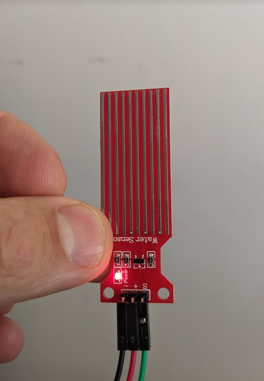
(2) I want the sensors to be attachable/detachable from the box. I am thinking of using these:
(3) I do I effectively turn that dupont pins + three cables (red sensor) AND the JST connector + 3 cables (green sensor) into a nice neat enclosed cable which will then end up with the 3-pin XLR plug? What parts do I need to buy?
Thank you very much! I hope I provided enough information. I spent literally hours writing this post... and learnt Fritzing just to post this today. I hope it will help.
Feel free to roast. I will most likely deserve it. Please keep in mind that I am a software engineer
You may get a bit of that from the anti-fritzing nazis which abound in these parts, but you should studiously ignore them. A bit of variety in the colour according the purpose of the wiring wouldn't go astray, though.
You may get value by grouping 0.1" terminal blocks on a blank proto shield.
I know nothing about the power requirements of the sensors, but imagine the Uno will get very uncomfortable running on 12v, 9v is a sensible maximum.
...why don't people like Fritzer? It's open source (although they charge for the service of compiling it... which is OK, you can still get it for free if you like), and it took me 20 minutes from learning it to drawing that chart...
What's an alternative? And BTW, did you see the improved version, with the colour coding of cables?
Because people too often make wiring diagrams with it that are confusing and difficult to read, as in your case, too. The way Fritzing is set up, it stimulates you to make wiring diagrams that approximate physical reality, which sounds intuitive enough, but it's usually a rather poor way of representing a circuit from a conceptual viewpoint.
In the end, both schematic diagrams and wiring diagrams have their purpose, but different ones.
Pencil and paper works quite well for schematics. Other free tools include LTSpice, DesignSpark PCB, KiCad and a whole slew of other tools that also offer schematic capture functionality. Some are easier to use than others. Some have additional functionality that make them worthwhile, such as simulation (LTSpice) or PCB design (DesignSpark, KiCad).
That'll work. Or you can make something with prototype board.
Heavy-duty, but should work fine, yes. I sometimes use DIN-type connectors (somewhat similar to your XLR ones) or RJ45 (network/UTP). RJ11 is also a possibility.
Hello,
nice project. I also have some of the same questions regarding cables and connectors, for a more permanent and robust way. Some ideas:
Regarding modules with Dupont pins, you can build this connectors:
You can create them yourself, and label each one to avoid connection 'accidents'
Dupont are not the best connectors, but many modules come with pin headers, and you can also solder some in a perfboard,
and add wiring interconnections and other headers and components, as a main connection board.
You have also this double row pcb headers:
With this jtag buses that you can also build.
There are also the JST connectors. But I don't like them much, sometimes they are hard to unplug. I use it only for batteries or solar panel.
You see more ideas in the Swiss accent guy channel:
If you are using Arduino Uno, for the final setup is better to move to arduino nano, or similar, on a perfboard with all the connectors and headers that you need.
But before you would connect and test all on a breadboard.
It's a wiring diagram or breadboard diagram. There are important differences.
Fritzing (not Fritzer) can make both. If you use it to make both, it will be easier because Fritzing can cross-check between the two to detect and highlight any discrepancies.
Having made your wiring/breadboard diagram in Fritzing, switch to schematic view and Fritzing will place all your components into the schematic and will show lines to indicate the connections you made on the wiring diagram. You can arrange the components and draw in the connections to make it look neat with minimal lengths and crossing connections.
Unlike other types of wiring diagram, in a schematic, the size, position and orientation of components does not need to reflect reality at all, so you can arrange and rotate your components to simplify and make the schematic easy to follow. All that matters in a schematic are the components, their values/part numbers and the connections between them. Therefore, components like breadboards, terminal blocks etc are usually not shown at all, because they don't change the operation of the circuit, so they are an irrelevant detail in a schematic (except maybe for connectors to separate components, boards or circuits).
A great way to de-clutter a schematic is to use power symbols like 5V, 3.3V, Gnd etc as many times as you like, close to the components or small groups of components that need them.
A lot of this is just snobbery, a case in point being here. That said, it is easy to make a mess with Fritzing and, the more complex your project gets, the more quickly and certainly that is going to happen. On the other hand, I rather feel that, if you are having grief turning out a decent Fritz, you are not likely to do any better with paper and pencil, and you will be amazed how many photographs get posted that tell you nothing.
I have not done it but, as noted above, Fritzing can turn out kosher schematic diagrams. Also as noted above, added text can work WONDERS. Nobody needs care about the colour code of a resistor, including you, when it is clearly marked 4k7.
Similarly, "9v 2A >" as an intent is a lot better than a picture of a 9v PP3 battery that is not your intent and you are only using because it is handy....


 Dupont wires")
