Following the official schematic from Texas Instrument (Attached), we are trying to built this LM2675-5.0 voltage regulator circuit. We have pretty much everything in exact according to the Bill of Materials, except
CIN. We don't have 15uF, 50V Tantalum cap. We are using a 470uF, 35V Electrolytic cap.
COUT. We don't have 68uF, 16V Tantalum cap. We are using a 68uF, 25V Tantalum cap.
When we activate the circuit, it correctly gives out 5V. Now, is there a way we can make sure the output is capable to supply 1A? What can we use as dummy load to verify our setup? Any thoughts?
Following the official schematic from Texas Instrument
Well it is not an official schematic it is an evaluation schematic. That means there may be things missing depending on how you use it and lay it out.
A good dummy load is some car side lights or some flash light bulbs.
Just checked with a dummy load, turned out the circuit only gives 200mA. What could be the issue? As we mentioned before out capacitors are not to spec. Will that affect the current output?
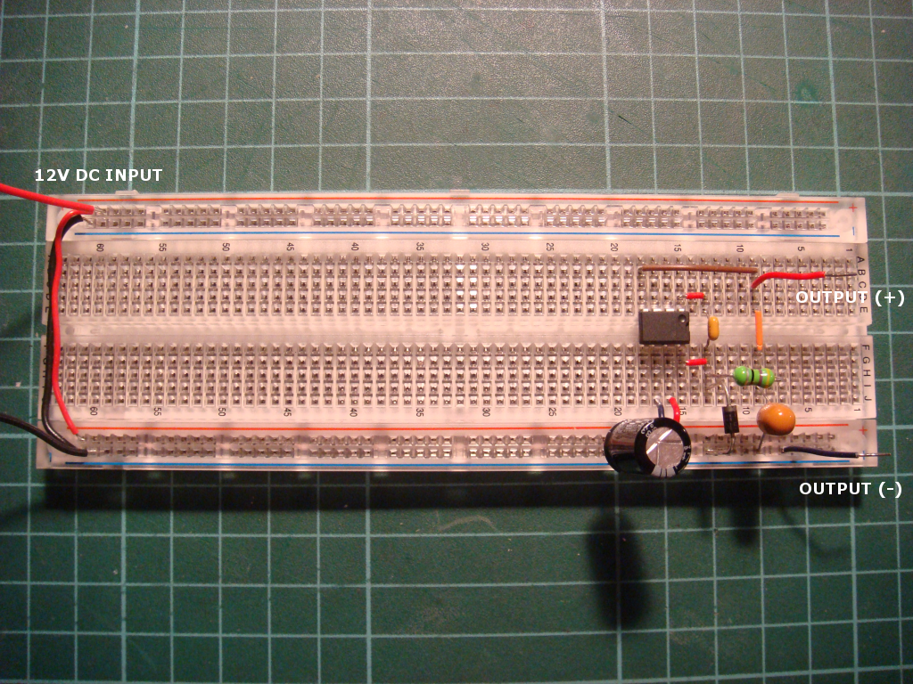
Our circuit is built according to the diagram I have on my original (1st post).
Yes but that was a schematic -- what is also important is physical placement of components and wiring. That is the thing that would be interesting to see.
--
The Rugged Circuits Yellowjacket: 802.11 WiFi module with ATmega328P microcontroller, only 1.6" x 1.2", bootloader
I'm beating RC to the punch** , but the datasheet shows that all of the components should be grounded to/at a central point. It's really particular and you need to concentrate on minimising component leads, too. There's a sample layout (at least in my datasheet). The breadboard is OK for low-power checkout, but for maximum performance a circuitboard is required. If nothing else, "deadbug" it.
** (I'd been lurking all along thinking that what you did was what you must've been doing.)
That inductor dosen't look like it is man enough to supply the current. You need one with a core that dosn't saturate.
Also like r_p says the layout is no where good enough for a switch mode power supply. You need a PCB and a correctly designed one as well.
Last night, we ended up removing everything from the breadboard, re-assemble everything from scratch on another portion of breadboard. Son of a gun, it worked.
We believe many things went wrong here such as layout, all caps, diode are at their full leads. We noticed during removal that some leads when inserted into breadboard, they went pass the contact rail underneath and slipped to somewhere else. There might be a short circuit somewhere, the circuit was giving a fluctuating 1.2V before we took everything out.
It is now running for more than 8 hours, the circuit is still stable and supplying voltage at 4.98V DC.
We use this power to drive a simple circuit consists of Photo transistor, op-amp, 7 Seg IC and 4x7 Segment LED display. Measuring no more than 75mA current. The staff is using the setup all day and I have no chance to verify the claimed 1A output.
How are you assessing that. Have you got a scope on any part of the circuit? If not you can't make that statement. Well you can but you have no evidence for it.