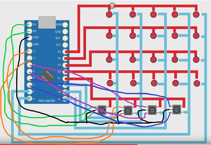
So I have a Arduino Pro Micro on the way. I've come across this video of a button box with 32 buttons total.
20 momentary push buttons / momentary toggle switches
4 rotary switches with push button.
What I'm trying to do is add 8 more momentary push buttons / momentary toggle switches taking the total to.
28 momentary push buttons / momentary toggle switches
4 rotary switches with push button.
This is how the 20 buttons and 4 rotary switches are wired in the post I was following. I need to know "If the buttons can be added how to wire them."
This is the code for the 20 buttons and 4 rotary switches with push button. I also need to know "If the other 8 buttons can be added how you would add it in the code."
//BUTTON BOX
//USE w ProMicro

#include <Keypad.h>
#include <Joystick.h>

#define ENABLE_PULLUPS
#define NUMROTARIES 4
#define NUMBUTTONS 24
#define NUMROWS 5
#define NUMCOLS 5


byte buttons[NUMROWS][NUMCOLS] = {
  {0,1,2,3,4},
  {5,6,7,8,9},
  {10,11,12,13,14},
  {15,16,17,18,19},
  {20,21,22,23},
};

struct rotariesdef {
  byte pin1;
  byte pin2;
  int ccwchar;
  int cwchar;
  volatile unsigned char state;
};

rotariesdef rotaries[NUMROTARIES] {
  {0,1,24,25,0},
  {2,3,26,27,0},
  {4,5,28,29,0},
  {6,7,30,31,0},
};

#define DIR_CCW 0x10
#define DIR_CW 0x20
#define R_START 0x0

#ifdef HALF_STEP
#define R_CCW_BEGIN 0x1
#define R_CW_BEGIN 0x2
#define R_START_M 0x3
#define R_CW_BEGIN_M 0x4
#define R_CCW_BEGIN_M 0x5
const unsigned char ttable[6][4] = {
  // R_START (00)
  {R_START_M,            R_CW_BEGIN,     R_CCW_BEGIN,  R_START},
  // R_CCW_BEGIN
  {R_START_M | DIR_CCW, R_START,        R_CCW_BEGIN,  R_START},
  // R_CW_BEGIN
  {R_START_M | DIR_CW,  R_CW_BEGIN,     R_START,      R_START},
  // R_START_M (11)
  {R_START_M,            R_CCW_BEGIN_M,  R_CW_BEGIN_M, R_START},
  // R_CW_BEGIN_M
  {R_START_M,            R_START_M,      R_CW_BEGIN_M, R_START | DIR_CW},
  // R_CCW_BEGIN_M
  {R_START_M,            R_CCW_BEGIN_M,  R_START_M,    R_START | DIR_CCW},
};
#else
#define R_CW_FINAL 0x1
#define R_CW_BEGIN 0x2
#define R_CW_NEXT 0x3
#define R_CCW_BEGIN 0x4
#define R_CCW_FINAL 0x5
#define R_CCW_NEXT 0x6

const unsigned char ttable[7][4] = {
  // R_START
  {R_START,    R_CW_BEGIN,  R_CCW_BEGIN, R_START},
  // R_CW_FINAL
  {R_CW_NEXT,  R_START,     R_CW_FINAL,  R_START | DIR_CW},
  // R_CW_BEGIN
  {R_CW_NEXT,  R_CW_BEGIN,  R_START,     R_START},
  // R_CW_NEXT
  {R_CW_NEXT,  R_CW_BEGIN,  R_CW_FINAL,  R_START},
  // R_CCW_BEGIN
  {R_CCW_NEXT, R_START,     R_CCW_BEGIN, R_START},
  // R_CCW_FINAL
  {R_CCW_NEXT, R_CCW_FINAL, R_START,     R_START | DIR_CCW},
  // R_CCW_NEXT
  {R_CCW_NEXT, R_CCW_FINAL, R_CCW_BEGIN, R_START},
};
#endif

byte rowPins[NUMROWS] = {21,20,19,18,15};
byte colPins[NUMCOLS] = {14,16,10,9,8};

Keypad buttbx = Keypad( makeKeymap(buttons), rowPins, colPins, NUMROWS, NUMCOLS);

Joystick_ Joystick(JOYSTICK_DEFAULT_REPORT_ID,
  JOYSTICK_TYPE_JOYSTICK, 32, 0,
  false, false, false, false, false, false,
  false, false, false, false, false);

void setup() {
  Joystick.begin();
  rotary_init();}

void loop() {

  CheckAllEncoders();

  CheckAllButtons();

}

void CheckAllButtons(void) {
      if (buttbx.getKeys())
    {
       for (int i=0; i<LIST_MAX; i++)
        {
           if ( buttbx.key[i].stateChanged )
            {
            switch (buttbx.key[i].kstate) {
                    case PRESSED:
                    case HOLD:
                              Joystick.setButton(buttbx.key[i].kchar, 1);
                              break;
                    case RELEASED:
                    case IDLE:
                              Joystick.setButton(buttbx.key[i].kchar, 0);
                              break;
            }
           }
         }
     }
}


void rotary_init() {
  for (int i=0;i<NUMROTARIES;i++) {
    pinMode(rotaries[i].pin1, INPUT);
    pinMode(rotaries[i].pin2, INPUT);
    #ifdef ENABLE_PULLUPS
      digitalWrite(rotaries[i].pin1, HIGH);
      digitalWrite(rotaries[i].pin2, HIGH);
    #endif
  }
}


unsigned char rotary_process(int _i) {
   unsigned char pinstate = (digitalRead(rotaries[_i].pin2) << 1) | digitalRead(rotaries[_i].pin1);
  rotaries[_i].state = ttable[rotaries[_i].state & 0xf][pinstate];
  return (rotaries[_i].state & 0x30);
}

void CheckAllEncoders(void) {
  for (int i=0;i<NUMROTARIES;i++) {
    unsigned char result = rotary_process(i);
    if (result == DIR_CCW) {
      Joystick.setButton(rotaries[i].ccwchar, 1); delay(50); Joystick.setButton(rotaries[i].ccwchar, 0);
    };
    if (result == DIR_CW) {
      Joystick.setButton(rotaries[i].cwchar, 1); delay(50); Joystick.setButton(rotaries[i].cwchar, 0);
    };
  }
}
Thanks in advance for any help and hopefully I posted this all per forum guidelines.

