I am trying to program it so that when a button is pushed it sends current out of 5 pins. Then it is a random delay before it randomly turns off when of the currents (going to be lights in thoose, so a random light will turn off after a random time).
Here is the code I have:
int randomLight = 2 + (rand() % 5);
int randomTime = 15000 + (rand() % 90000);
const int buttonPin = 7;
const int ledPinOne = 2;
const int ledPinTwo = 3;
const int ledPinThree = 4;
const int ledPinFour = 5;
const int ledPinFive = 6;


void setup() {
  pinMode(buttonPin, INPUT_PULLUP);

  pinMode(ledPinOne, OUTPUT);
  pinMode(ledPinTwo, OUTPUT);
  pinMode(ledPinThree, OUTPUT);
  pinMode(ledPinFour, OUTPUT);
  pinMode(ledPinFive, OUTPUT);

}

void loop() {
  if (digitalRead(buttonPin) == LOW)
  {
  digitalWrite(ledPinOne, HIGH);
  digitalWrite(ledPinTwo, HIGH);
  digitalWrite(ledPinThree, HIGH);
  digitalWrite(ledPinFour, HIGH);
  digitalWrite(ledPinFive, HIGH);
  delay(randomTime);
  digitalWrite(randomLight, LOW);
  }
}
No lights are turning on. What have I done wron and how could I have written the code so that it works?
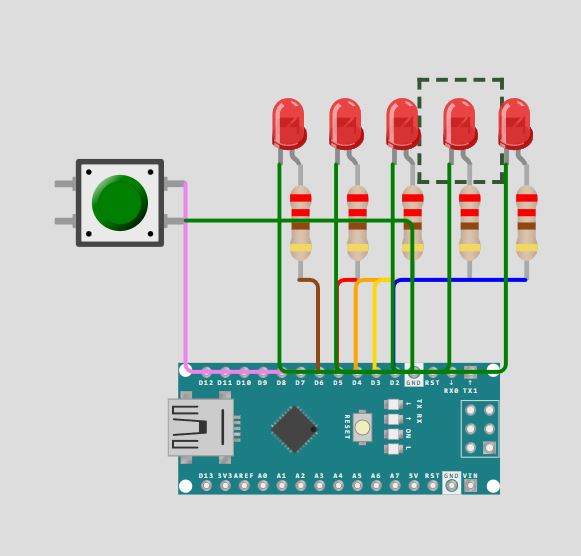
Something like in the picture. But don't use led with resistance like that. It is going to be one cable out from each of the pins 2-7 with the button on 7 and then all of them connected to ground.
Ah, that is true. Thanks, missed that I had to update the value when the button is pressed. But it doesn't solve it fully. My first problem is that nothing happens when I push the button. It doesn't even turn on the lights.
But then they should need to be inside the if statement?
I hope you don't mean you are not using a series current limiting resistor one for each LED.
That would be okay, but where they are it's like shuffling the dice 1000s of times a second.
Practically speaking makes no difference. But it's a nice trick to remember, a way of using real world events (how long is a button pressed, or how long since it has been) to scramble things real good.
I can't run that code, but I'd bet you breakfast that the interval is identical every time. Maybe even the very same the every time you restart the code.
Post a simple sketch like your last one, with your attemtp to make it controlled by pushbutton.
It's hard to see, so I assume your switch is wired between digital pin 7 and GND. Looks like it should work…
I was going to use the time I am waiting for she who must never be kept waiting (irony defined) to lash up your project and run your code.
All I managed was to find that rand() returns an int, values between including 0 to 32767.
You should use random() instead. The you could also use
int x = random(42); // returns random # 0 ... 41
or
int x = random(42, 99); // returns random # 42 ... 98
or
int x = random(); // returns random # 0 ... 2147483647
So you don't need the modulo operator.
Later we can talk about a better way to handle LEDs on five pins. What you are doing is convenient but relies on some things that may end up being inconvenient. No worries for now.
Sorry, just copied my old code and explained it a bit bad. My point with this was only that the light and board works and everything is connected correctly. So I have eliminated that.
If you find real life to differ from the wokwi, suspect first that it is your problem IRL but post a link to the simulation. There are very interested ppl who want to make it perfecter.
@wineitot I'm at the beach, but I did try to clean up your wiring... you can move wires around after if you place them badly first time. Just select the wire. Use the little dots to drag it until you're happy. It makes it easier to see where the wires actually go.
I tried. It doesn't work too well on my atblet. BUT I did see when I moved a LED that they are not connected in the circuit.
You need to wire between the components, not just get them visually close.
Ah, thank you. Then the problem is solved. Just bad interface on the page then. I got tricked by the components attaching to each other, so it seemed like they were connected.