system
February 15, 2014, 1:02pm
1
I'm trying to measure resistance with arduino Nano ATMega328, it works on paper, but Arduino doesn't somehow calculate the resistance. LCD output: Voltage: 1.73 R1: -24495
Schematic and princible is here (first circuit picture):http://iwantmyreal.name/blog/2012/09/23/measuring-the-temperature-with-an-arduino-and-a-thermistor/
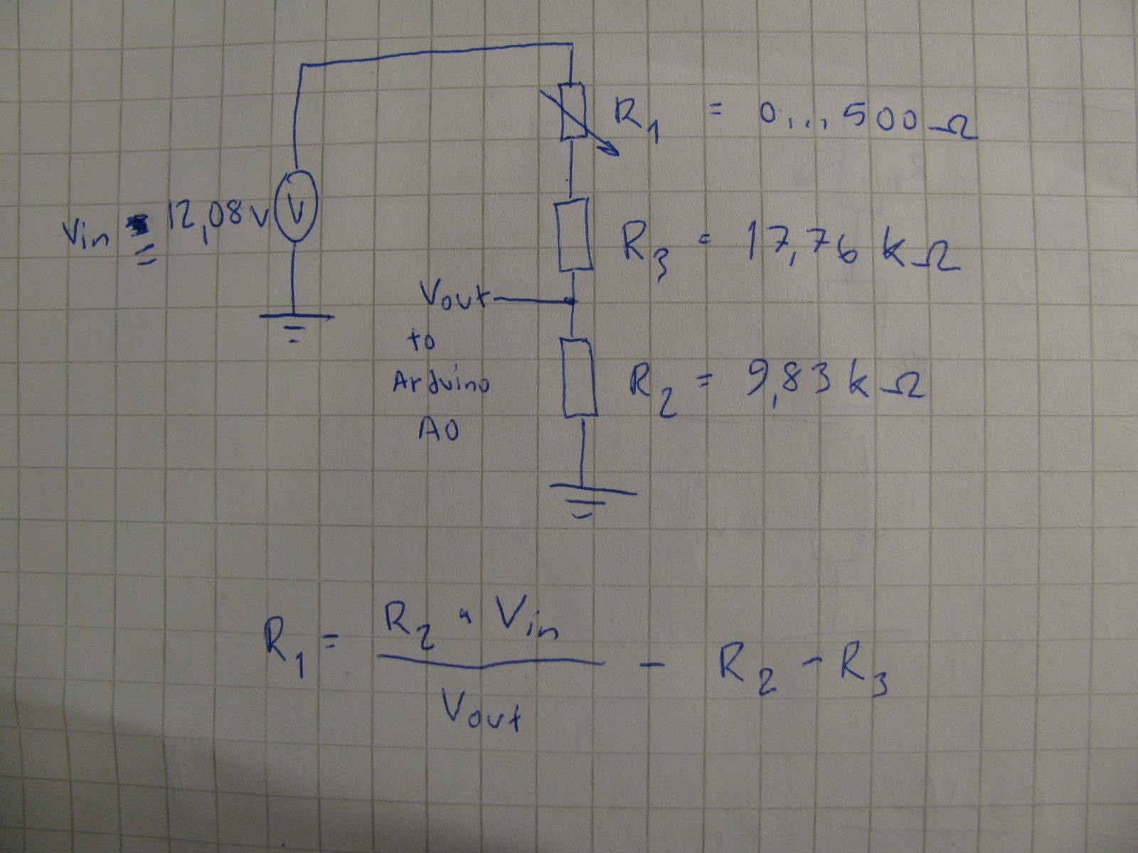
R3 is in series with R1 to lower 12.08 voltage for arduino, so:
Code:
}
system
February 15, 2014, 1:14pm
2
What do you think R2 should be? Does that value actually fit in an int?
Hi, can you please use code /code tags to post your code.
Tom......
system
February 15, 2014, 2:16pm
4
Yes, the 17,76 kohm is calculated with Vin 12.08 V and gives 4.3 V Vout when R1 is 500 ohm.
-LS
system
February 15, 2014, 3:04pm
5
Your equation for calculating R1 is wrong. Wikipedia gives a formula for two resistors:
You have two resistors on the Z1 side, so Z1 = R1 + R3 and Z2 = R2.
Plugging that in gives:
Vout + Vin = R2/(R2 + R1 + R3)
R2 + R1 + R3 = R2/(Vout + Vin);
R1 = R2/(Vout + Vin) - R2 - R3
system
February 15, 2014, 3:21pm
8
Tried this as a part of the code, but it gives still incorrect ansver R1 : -26129
R1 = (R2)/(Vout + Vin) - R2 - R3;
JimboZA
February 15, 2014, 3:27pm
9
Paul's equation is wrong since he misread the equation in Wikipedia.
Tbird, your equation in your pic correctly solves for R1.
system
February 15, 2014, 3:47pm
10
Thanks, I thought so because I solved it on paper. Thanks for all! Now back to calibration plans.
-LS