I am using a Pololu AltIMU 10 v5 using jremington's GitHub AHRS code. The magnetometer, accelerometer, and gyro have been calibrated. The problem is that when I rotate the sensor it completes a full 360 degrees, but it is not visually perpendicular at 90,180, and 270 degrees. The compass also does not compensate for the roll and pitch. However, the roll and pitch angles are working as expected. I have tried calibrating the accelerometer and magnetometer several times without any differences. Is there something I'm missing? I'm almost certain that the IMU does not have flipped axes. Any input on this subject would be greatly appreciated.
Most likely, the magnetometer calibration is not correct. Several steps are involved and it is easy to make a mistake.
Please describe the procedure you used for calibrating the magnetometer, post the results, a code snippet showing how the results were entered and the test data used for the calibration.
Edit: I just noticed the mention of the Altimu 10-V5. The code I wrote is for the V3, which uses different sensors.
For the Magnetometer: I print data in Gauss to a Serial monitor which records the data to a txt file. While data is being recorded I slowly revolve the sensor around an imaginary sphere. There is no specific pattern to how I do this but I attempt to cover as many points of the spare as possible. After about three minutes, I stop recording data and go through the txt file to ensure all the data printed correctly, (sometimes the first and last lines are cut off, hence, wrong values). I use Magneto software to output the correction matrix. (I ensured that I used the correct units for the Norm of the Magnetic or Gravitational field input box). After that, I copy and paste the correction values into the code. For the Accelerometer: I used a similar procedure except that the measurements recorded were while the sensor wasn't moving. To do this I stood up the sensor at different angles and recorded a single measurement at a time. The code I modified to work for the AltIMU 10-V5. You can see what I added and deleted:
//Added
#include <SoftwareWire.h>

//
// AltIMU-10 v3 Magwick/Mahony AHRS  S.J. Remington
// last update 12/17/2020, clean up comments
// See: http://www.x-io.co.uk/open-source-imu-and-ahrs-algorithms/
// Standard sensor orientation: Z Up X North Y West

// Both the accelerometer and magnetometer MUST be properly calibrated for this program to work, and the gyro offset must be determined.
// Follow the procedure described in http://sailboatinstruments.blogspot.com/2011/08/improved-magnetometer-calibration.html
// or in more detail, the tutorial https://thecavepearlproject.org/2015/05/22/calibrating-any-compass-or-accelerometer-for-arduino/
// To collect data for calibration, use the companion programs altimu10v3_cal and Magneto 1.2 from sailboatinstruments.blogspot.com
//

// Added
SoftwareWire myWire (3,2); // SDA, SCL

// Added
uint8_t gxl, gxh, gyl, gyh, gzl, gzh, axl, axh, ayl, ayh, azl, azh, mxl, mxh, myl, myh, mzl, mzh, pxl, pl, ph;
int16_t gx, gy, gz, ax, ay, az, mx, my, mz;
int32_t p;
float mbar;

// vvvvvvvvvvvvvvvvvv  VERY VERY IMPORTANT vvvvvvvvvvvvvvvvvvvvvvvvvvvvv
//These are the previously determined offsets (bias) and scale factors for accelerometer and magnetometer,
// using altimu10v3_cal and Magneto 1.2 or 1.3
//The AHRS will NOT work well or at all if these are not correct
//-------------Modified------------
float M_B[3] {   -0.075535,  -0.062595,   0.031614}; //mag offsets and scale
float M_Ainv[3][3]
{ {  1.040671,  0.012446,  -0.005234},
  {  0.012446,  1.029135, 0.002737},
  {  -0.005234, 0.002737,  1.091716}
};
//-------------Modified------------
float A_B[3] { 0.003342, -0.006250, 0.030219}; //accelerometer offsets and scale
float A_Ainv[3][3]
{ {  1.004623,  0.002923,  -0.006355},
  {  0.002923,  1.009054, 0.001762},
  {  -0.006355, 0.001762,  0.995992}
};

//The L3GD20H default full scale setting is +/- 245 dps.
//-------------Modified------------
#define gscale 17.5e-3*(PI/180.0)  //gyro default 8.75 mdps -> rad/s Me: This is correct.

//-------------Modified------------
float G_off[3] = {33.1360015869, -66.9879989624, -48.1570014953}; //raw offsets, determined for gyro at rest
// ^^^^^^^^^^^^^^^^^^^ VERY VERY IMPORTANT ^^^^^^^^^^^^^^^^^^^^^^^^^^^^^^

char s[60]; //snprintf buffer

// globals for AHRS loop timing
unsigned long now = 0, last = 0; //micros() timers
float deltat = 0;  //loop time in seconds
unsigned long now_ms, last_ms = 0; //millis() timers
unsigned long print_ms = 1; //print orientation angles every "print_ms" milliseconds

//raw data and scaled as vector
float Axyz[3];
float Gxyz[3];
float Mxyz[3];


// NOW USING MAHONY FILTER

// These are the free parameters in the Mahony filter and fusion scheme,
// Kp for proportional feedback, Ki for integral
// with MPU-9250, angles start oscillating at Kp=40. Ki does not seem to help and is not required.

//-------------Modified------------
#define Kp 45.0
#define Ki 0.0

// Vector to hold quaternion
static float q[4] = {1.0, 0.0, 0.0, 0.0};
static float yaw, pitch, roll; //Euler angle output

void setup() {

//Added
  myWire.begin();
  Serial.begin(9600);
  init_10DOF_sensor();

// AHRS loop
}
void loop()
{
  static int i = 0, count=0;
  float qw, qx, qy, qz;

  get_IMU_scaled();
  now = micros();
  deltat = (now - last) * 1.0e-6; //seconds since last update
  last = now;

  MahonyQuaternionUpdate(Axyz[0], Axyz[1], Axyz[2], Gxyz[0], Gxyz[1], Gxyz[2],
                         Mxyz[0], Mxyz[1], Mxyz[2], deltat);

// Define Tait-Bryan angles. Strictly valid only for approximately level flight


//  Tait-Bryan angles as well as Euler angles are
// non-commutative; that is, the get the correct orientation the rotations
// must be applied in the correct order which for this configuration is yaw,
// pitch, and then roll.
// http://en.wikipedia.org/wiki/Conversion_between_quaternions_and_Euler_angles
// which has additional links.

      // WARNING: This angular conversion is for DEMONSTRATION PURPOSES ONLY. It WILL
      // MALFUNCTION for certain combinations of angles! See https://en.wikipedia.org/wiki/Gimbal_lock

  roll  = atan2((q[0] * q[1] + q[2] * q[3]), 0.5 - (q[1] * q[1] + q[2] * q[2]));
  pitch = asin(2.0 * (q[0] * q[2] - q[1] * q[3]));
  yaw   = atan2((q[1] * q[2] + q[0] * q[3]), 0.5 - ( q[2] * q[2] + q[3] * q[3]));

  // to degrees
  yaw   *= 180.0 / PI;
  pitch *= 180.0 / PI;
  roll *= 180.0 / PI;

  // http://www.ngdc.noaa.gov/geomag-web/#declination
  //conventional nav, yaw increases CW from North, corrected for local magnetic declination
  //---------Modified---------
  yaw = -yaw + 5.46;

  if (yaw > 360.0) yaw -= 360.0;
  if (yaw < 0) yaw += 360.0;
  count++; //loop iterations
  now_ms = millis(); //time to print?
  if (now_ms - last_ms >= print_ms)
  {
    last_ms = now_ms;
    // print angles for serial plotter...
    //  Serial.print("ypr ");
    Serial.print(yaw, 0);
    Serial.print(", ");
    Serial.print(pitch, 0);
    Serial.print(", ");
    Serial.println(roll, 0);
//    Serial.print(", ");
//    Serial.println(count); //number of loop iterations in this print interval (about 90 with 16 MHz Pro Mini)
    count=0;
  }
}
void get_IMU_scaled(void) {

//Added
 read_10DOF_sensor();

//-----Modified-----
  byte i;
  float temp[3];
  Axyz[0] = ax;
  Axyz[1] = ay;
  Axyz[2] = az;
  Mxyz[0] = mx;
  Mxyz[1] = my;
  Mxyz[2] = mz;
  Gxyz[0] = gx;
  Gxyz[1] = gy;
  Gxyz[2] = gz;

  //apply offsets (bias) and scale factors from Magneto
  for (i = 0; i < 3; i++) temp[i] = (Axyz[i] - A_B[i]);
  Axyz[0] = A_Ainv[0][0] * temp[0] + A_Ainv[0][1] * temp[1] + A_Ainv[0][2] * temp[2];
  Axyz[1] = A_Ainv[1][0] * temp[0] + A_Ainv[1][1] * temp[1] + A_Ainv[1][2] * temp[2];
  Axyz[2] = A_Ainv[2][0] * temp[0] + A_Ainv[2][1] * temp[1] + A_Ainv[2][2] * temp[2];
  vector_normalize(Axyz);

  //apply offsets (bias) and scale factors from Magneto
  for (int i = 0; i < 3; i++) temp[i] = (Mxyz[i] - M_B[i]);
  Mxyz[0] = M_Ainv[0][0] * temp[0] + M_Ainv[0][1] * temp[1] + M_Ainv[0][2] * temp[2];
  Mxyz[1] = M_Ainv[1][0] * temp[0] + M_Ainv[1][1] * temp[1] + M_Ainv[1][2] * temp[2];
  Mxyz[2] = M_Ainv[2][0] * temp[0] + M_Ainv[2][1] * temp[1] + M_Ainv[2][2] * temp[2];
  vector_normalize(Mxyz);

  Gxyz[0] = ((float) gx - G_off[0]) * gscale; //d/s to radians/s
  Gxyz[1] = ((float) gy - G_off[1]) * gscale;
  Gxyz[2] = ((float) gz - G_off[2]) * gscale;
  }

// Mahony scheme uses proportional and integral filtering on
// the error between estimated reference vectors and measured ones.
//-----Modified Inputs-----
void MahonyQuaternionUpdate(float ax, float ay, float az, float gx, float gy, float gz, float mx, float my, float mz, float deltat)
{
 // Vector to hold integral error for Mahony method
  static float eInt[3] = {0.0, 0.0, 0.0};
// short name local variable for readability
  float q1 = q[0], q2 = q[1], q3 = q[2], q4 = q[3];
  float norm;
  float hx, hy, bx, bz;
  float vx, vy, vz, wx, wy, wz;
  float ex, ey, ez;
  float pa, pb, pc;

  // Auxiliary variables to avoid repeated arithmetic
  float q1q1 = q1 * q1;
  float q1q2 = q1 * q2;
  float q1q3 = q1 * q3;
  float q1q4 = q1 * q4;
  float q2q2 = q2 * q2;
  float q2q3 = q2 * q3;
  float q2q4 = q2 * q4;
  float q3q3 = q3 * q3;
  float q3q4 = q3 * q4;
  float q4q4 = q4 * q4;
  /*
    // already done in loop()

    // Normalise accelerometer measurement
    norm = sqrt(ax * ax + ay * ay + az * az);
    if (norm == 0.0f) return; // Handle NaN
    norm = 1.0f / norm;       // Use reciprocal for division
    ax *= norm;
    ay *= norm;
    az *= norm;

    // Normalise magnetometer measurement
    norm = sqrt(mx * mx + my * my + mz * mz);
    if (norm == 0.0f) return; // Handle NaN
    norm = 1.0f / norm;       // Use reciprocal for division
    mx *= norm;
    my *= norm;
    mz *= norm;
  */
  // Reference direction of Earth's magnetic field
  hx = 2.0f * mx * (0.5f - q3q3 - q4q4) + 2.0f * my * (q2q3 - q1q4) + 2.0f * mz * (q2q4 + q1q3);
  hy = 2.0f * mx * (q2q3 + q1q4) + 2.0f * my * (0.5f - q2q2 - q4q4) + 2.0f * mz * (q3q4 - q1q2);
  bx = sqrt((hx * hx) + (hy * hy));
  bz = 2.0f * mx * (q2q4 - q1q3) + 2.0f * my * (q3q4 + q1q2) + 2.0f * mz * (0.5f - q2q2 - q3q3);

  // Estimated direction of gravity and magnetic field
  vx = 2.0f * (q2q4 - q1q3);
  vy = 2.0f * (q1q2 + q3q4);
  vz = q1q1 - q2q2 - q3q3 + q4q4;
  wx = 2.0f * bx * (0.5f - q3q3 - q4q4) + 2.0f * bz * (q2q4 - q1q3);
  wy = 2.0f * bx * (q2q3 - q1q4) + 2.0f * bz * (q1q2 + q3q4);
  wz = 2.0f * bx * (q1q3 + q2q4) + 2.0f * bz * (0.5f - q2q2 - q3q3);

  // Error is cross product between estimated direction and measured direction of gravity
  ex = (ay * vz - az * vy) + (my * wz - mz * wy);
  ey = (az * vx - ax * vz) + (mz * wx - mx * wz);
  ez = (ax * vy - ay * vx) + (mx * wy - my * wx);
  if (Ki > 0.0f)
  {
    eInt[0] += ex;      // accumulate integral error
    eInt[1] += ey;
    eInt[2] += ez;
  }
  else
  {
    eInt[0] = 0.0f;     // prevent integral wind up
    eInt[1] = 0.0f;
    eInt[2] = 0.0f;
  }

  // Apply feedback terms to gyro rate measurement
  gx = gx + Kp * ex + Ki * eInt[0];
  gy = gy + Kp * ey + Ki * eInt[1];
  gz = gz + Kp * ez + Ki * eInt[2];


 //update quaternion with integrated contribution
 // small correction 1/11/2022, see https://github.com/kriswiner/MPU9250/issues/447
gx = gx * (0.5*deltat); // pre-multiply common factors
gy = gy * (0.5*deltat);
gz = gz * (0.5*deltat);
float qa = q1;
float qb = q2;
float qc = q3;
q1 += (-qb * gx - qc * gy - q4 * gz);
q2 += (qa * gx + qc * gz - q4 * gy);
q3 += (qa * gy - qb * gz + q4 * gx);
q4 += (qa * gz + qb * gy - qc * gx);

  // Normalise quaternion
  norm = sqrt(q1 * q1 + q2 * q2 + q3 * q3 + q4 * q4);
  norm = 1.0f / norm;
  q[0] = q1 * norm;
  q[1] = q2 * norm;
  q[2] = q3 * norm;
  q[3] = q4 * norm;
}

float vector_dot(float a[3], float b[3])
{
  return a[0] * b[0] + a[1] * b[1] + a[2] * b[2];
}

void vector_normalize(float a[3])
{
  float mag = sqrt(vector_dot(a, a));
  a[0] /= mag;
  a[1] /= mag;
  a[2] /= mag;
}

//Added
void init_10DOF_sensor() {

  myWire.beginTransmission(0x6B);  // config accelerometer
  myWire.write(0x10);
  myWire.write(0b10100000);
  myWire.endTransmission();

  myWire.beginTransmission(0x6B);  // config gyro
  myWire.write(0x11);
  myWire.write(0b10100100);
  myWire.endTransmission();

  myWire.beginTransmission(0x1E);  // config magnetometer
  myWire.write(0x20);              // contr reg 1
  myWire.write(0b11111100);
  myWire.endTransmission();

  myWire.beginTransmission(0x1E);  // config magnetometer
  myWire.write(0x21);              // contr reg 2
  myWire.write(0b00000000);
  myWire.endTransmission();

  myWire.beginTransmission(0x1E);  // config magnetometer
  myWire.write(0x22);              // contr reg 3
  myWire.write(0b00000000);
  myWire.endTransmission();

  myWire.beginTransmission(0x1E);  // config magnetometer
  myWire.write(0x23);              // contr reg 4
  myWire.write(0b00001100);
  myWire.endTransmission();

  myWire.beginTransmission(0x5D);  //config barometer
  myWire.write(0x20);
  myWire.write(0b11000000);
  myWire.endTransmission();
}

//Added
void read_10DOF_sensor() {

  myWire.beginTransmission(0x6B);
  myWire.write(0x22);
  myWire.endTransmission();

  myWire.requestFrom(0x6B, 12);

  if (myWire.available()) {

    gxl = myWire.read();
    gxh = myWire.read();
    gyl = myWire.read();
    gyh = myWire.read();
    gzl = myWire.read();
    gzh = myWire.read();

    axl = myWire.read();
    axh = myWire.read();
    ayl = myWire.read();
    ayh = myWire.read();
    azl = myWire.read();
    azh = myWire.read();

    gx = gxh << 8 | gxl;
    gy = gyh << 8 | gyl;
    gz = gzh << 8 | gzl;

    ax = axh << 8 | axl;
    ay = ayh << 8 | ayl;
    az = azh << 8 | azl;
  }

  myWire.beginTransmission(0x1E);
  myWire.write(0x28);
  myWire.endTransmission();

  myWire.requestFrom(0x1E, 6);

  if (myWire.available()) {

    mxl = myWire.read();
    mxh = myWire.read();
    myl = myWire.read();
    myh = myWire.read();
    mzl = myWire.read();
    mzh = myWire.read();

    mx = mxh << 8 | mxl;
    my = myh << 8 | myl;
    mz = mzh << 8 | mzl;

    myWire.beginTransmission(0x5D);
    myWire.write(0x28 | 0b10000000);
    myWire.endTransmission();

    myWire.requestFrom(0x5D, 3);

    pxl = myWire.read();
    pl = myWire.read();
    ph = myWire.read();

    p = (int32_t)ph << 16 | (int32_t)pl << 8 | (int32_t)pxl;

    mbar = (float)(p / 4096.0);
  }
}
I find it difficult to believe that the magnetometer and accelerometer offsets are that small. The measurements should be raw integers (not scaled or corrected in any way by the chips).
Check that when the corrections are applied, the resulting corrected data map to a sphere perfectly centered on the origin.
Also check that, as mounted on the sensor PCB, the magnetometer chip and accelerometer chip axial alignments are consistent and agree with the axis markings on the PCB.
Especially for the magnetometer, check that the raw data vectors point in a direction consistent with the Earth's magnetic field vector in your location (which you can look up on line). In the northern hemisphere, that vector points rather steeply down, into the ground, as well as North.
Where could I find an easy-to-use magnetometer 3D data plotter? I have seen pictures of magnetometer data plotted, but I don't know what software should be used.
The Python calibration and plot code I posted on the Github site works well. You will have to edit the name of the input data file, which is hard wired into the code.
Ok, thank you.
Here is what I got:
(Uncalibrated)
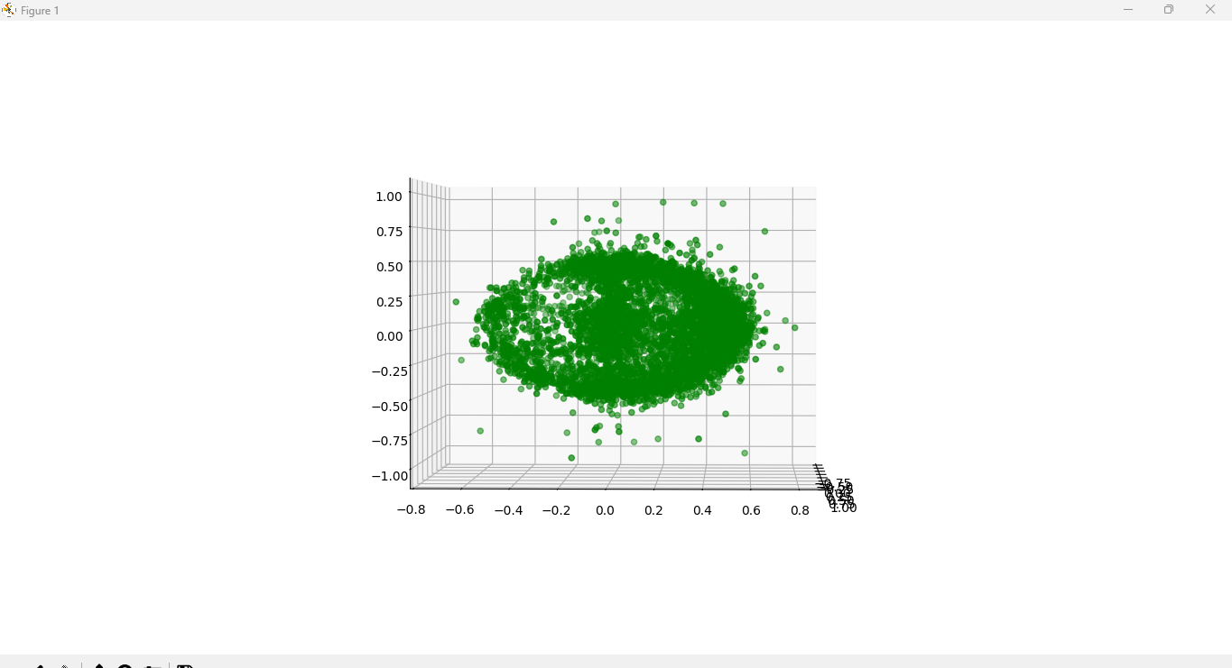
(Calibrated)
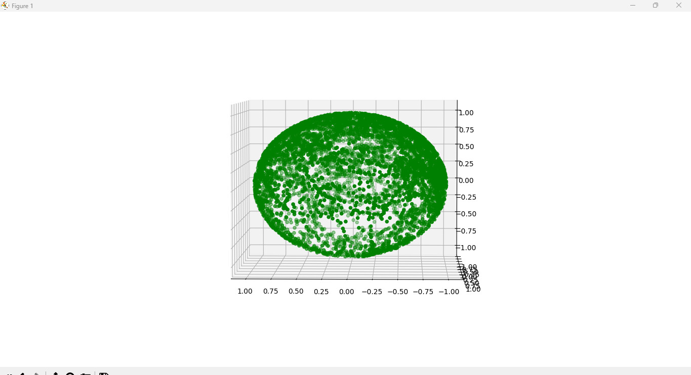
In the calibrated picture I set the Mfield to 1. The total Magnetic field vector in Guass equals 0.52743 where I live. (I changed the Mfield to this number when I calibrated the uncalibrated data). For some reason, the calibrated picture looks more like an ellipsoid than a sphere. But when I put the corrected calibration numbers into the code, the compass started to work properly. I probably was doing something wrong the entire time, because when I used the Magneto software to calibrate the data I got similar results to what your code gave me. Anyway, thank you very much for helping me and the community with the resources you have provided. Here is my code with the Corrected Magnetometer calibration numbers:
#include <SoftwareWire.h>

//
// AltIMU-10 v3 Magwick/Mahony AHRS  S.J. Remington
// last update 12/17/2020, clean up comments
// See: http://www.x-io.co.uk/open-source-imu-and-ahrs-algorithms/
// Standard sensor orientation: Z Up X North Y West

// Both the accelerometer and magnetometer MUST be properly calibrated for this program to work, and the gyro offset must be determned.
// Follow the procedure described in http://sailboatinstruments.blogspot.com/2011/08/improved-magnetometer-calibration.html
// or in more detail, the tutorial https://thecavepearlproject.org/2015/05/22/calibrating-any-compass-or-accelerometer-for-arduino/
// To collect data for calibration, use the companion programs altimu10v3_cal and Magneto 1.2 from sailboatinstruments.blogspot.com
//

// Added
SoftwareWire myWire (3,2); // SDA, SCL

// Added
uint8_t gxl, gxh, gyl, gyh, gzl, gzh, axl, axh, ayl, ayh, azl, azh, mxl, mxh, myl, myh, mzl, mzh, pxl, pl, ph;
int16_t gx, gy, gz, ax, ay, az, mx, my, mz;
int32_t p;
float mbar;

// vvvvvvvvvvvvvvvvvv  VERY VERY IMPORTANT vvvvvvvvvvvvvvvvvvvvvvvvvvvvv
//These are the previously determined offsets (bias) and scale factors for accelerometer and magnetometer,
// using altimu10v3_cal and Magneto 1.2 or 1.3
//The AHRS will NOT work well or at all if these are not correct
//-------------Modified------------
float M_B[3] {   0.00395381,  -0.00063741,   0.0364596}; //mag offsets and scale
float M_Ainv[3][3]
{ {  0.52640537,  -0.00117927,  -0.0037056},
  {  -0.00117927,  0.54084412, -0.0066077},
  {  -0.0037056, -0.0066077,  0.48885089}
};
//-------------Modified------------
float A_B[3] { 0.003342, -0.006250, 0.030219}; //accelerometer offsets and scale
float A_Ainv[3][3]
{ {  1.004623,  0.002923,  -0.006355},
  {  0.002923,  1.009054, 0.001762},
  {  -0.006355, 0.001762,  0.995992}
};

//The L3GD20H default full scale setting is +/- 245 dps.
//-------------Modified------------
#define gscale 17.5e-3*(PI/180.0)  //gyro default 8.75 mdps -> rad/s Me: This is correct.

//-------------Modified------------
float G_off[3] = {33.1360015869, -66.9879989624, -48.1570014953}; //raw offsets, determined for gyro at rest
// ^^^^^^^^^^^^^^^^^^^ VERY VERY IMPORTANT ^^^^^^^^^^^^^^^^^^^^^^^^^^^^^^

char s[60]; //snprintf buffer

// globals for AHRS loop timing
unsigned long now = 0, last = 0; //micros() timers
float deltat = 0;  //loop time in seconds
unsigned long now_ms, last_ms = 0; //millis() timers
unsigned long print_ms = 1; //print orientation angles every "print_ms" milliseconds

//raw data and scaled as vector
float Axyz[3];
float Gxyz[3];
float Mxyz[3];


// NOW USING MAHONY FILTER

// These are the free parameters in the Mahony filter and fusion scheme,
// Kp for proportional feedback, Ki for integral
// with MPU-9250, angles start oscillating at Kp=40. Ki does not seem to help and is not required.

//-------------Modified------------
#define Kp 45.0
#define Ki 0.0

// Vector to hold quaternion
static float q[4] = {1.0, 0.0, 0.0, 0.0};
static float yaw, pitch, roll; //Euler angle output

void setup() {

//Added
  myWire.begin();
  Serial.begin(9600);
  init_10DOF_sensor();

// AHRS loop
}
void loop()
{
  static int i = 0, count=0;
  float qw, qx, qy, qz;

  get_IMU_scaled();
  now = micros();
  deltat = (now - last) * 1.0e-6; //seconds since last update
  last = now;

  MahonyQuaternionUpdate(Axyz[0], Axyz[1], Axyz[2], Gxyz[0], Gxyz[1], Gxyz[2],
                         Mxyz[0], Mxyz[1], Mxyz[2], deltat);

// Define Tait-Bryan angles. Strictly valid only for approximately level flight


//  Tait-Bryan angles as well as Euler angles are
// non-commutative; that is, the get the correct orientation the rotations
// must be applied in the correct order which for this configuration is yaw,
// pitch, and then roll.
// http://en.wikipedia.org/wiki/Conversion_between_quaternions_and_Euler_angles
// which has additional links.

      // WARNING: This angular conversion is for DEMONSTRATION PURPOSES ONLY. It WILL
      // MALFUNCTION for certain combinations of angles! See https://en.wikipedia.org/wiki/Gimbal_lock

  roll  = atan2((q[0] * q[1] + q[2] * q[3]), 0.5 - (q[1] * q[1] + q[2] * q[2]));
  pitch = asin(2.0 * (q[0] * q[2] - q[1] * q[3]));
  yaw   = atan2((q[1] * q[2] + q[0] * q[3]), 0.5 - ( q[2] * q[2] + q[3] * q[3]));

  // to degrees
  yaw   *= 180.0 / PI;
  pitch *= 180.0 / PI;
  roll *= 180.0 / PI;

  // http://www.ngdc.noaa.gov/geomag-web/#declination
  //conventional nav, yaw increases CW from North, corrected for local magnetic declination
  //---------Modified---------
  yaw = -yaw + 5.46;

  if (yaw > 360.0) yaw -= 360.0;
  if (yaw < 0) yaw += 360.0;
  count++; //loop iterations
  now_ms = millis(); //time to print?
  if (now_ms - last_ms >= print_ms)
  {
    last_ms = now_ms;
    // print angles for serial plotter...
    //  Serial.print("ypr ");
    Serial.print(yaw, 0);
    Serial.print(", ");
    Serial.print(pitch, 0);
    Serial.print(", ");
    Serial.println(roll, 0);

//    Serial.print(", ");
//    Serial.println(count); //number of loop iterations in this print interval (about 90 with 16 MHz Pro Mini)
    count=0;
  }
}
void get_IMU_scaled(void) {

//Added
 read_10DOF_sensor();

//-----Modified-----
  byte i;
  float temp[3];
  Axyz[0] = ax;
  Axyz[1] = ay;
  Axyz[2] = az;
  Mxyz[0] = mx;
  Mxyz[1] = my;
  Mxyz[2] = mz;
  Gxyz[0] = gx;
  Gxyz[1] = gy;
  Gxyz[2] = gz;

  //apply offsets (bias) and scale factors from Magneto
  for (i = 0; i < 3; i++) temp[i] = (Axyz[i] - A_B[i]);
  Axyz[0] = A_Ainv[0][0] * temp[0] + A_Ainv[0][1] * temp[1] + A_Ainv[0][2] * temp[2];
  Axyz[1] = A_Ainv[1][0] * temp[0] + A_Ainv[1][1] * temp[1] + A_Ainv[1][2] * temp[2];
  Axyz[2] = A_Ainv[2][0] * temp[0] + A_Ainv[2][1] * temp[1] + A_Ainv[2][2] * temp[2];
  vector_normalize(Axyz);

  //apply offsets (bias) and scale factors from Magneto
  for (int i = 0; i < 3; i++) temp[i] = (Mxyz[i] - M_B[i]);
  Mxyz[0] = M_Ainv[0][0] * temp[0] + M_Ainv[0][1] * temp[1] + M_Ainv[0][2] * temp[2];
  Mxyz[1] = M_Ainv[1][0] * temp[0] + M_Ainv[1][1] * temp[1] + M_Ainv[1][2] * temp[2];
  Mxyz[2] = M_Ainv[2][0] * temp[0] + M_Ainv[2][1] * temp[1] + M_Ainv[2][2] * temp[2];
  vector_normalize(Mxyz);

  Gxyz[0] = ((float) gx - G_off[0]) * gscale; //d/s to radians/s
  Gxyz[1] = ((float) gy - G_off[1]) * gscale;
  Gxyz[2] = ((float) gz - G_off[2]) * gscale;
  }

// Mahony scheme uses proportional and integral filtering on
// the error between estimated reference vectors and measured ones.
//-----Modified Inputs-----
void MahonyQuaternionUpdate(float ax, float ay, float az, float gx, float gy, float gz, float mx, float my, float mz, float deltat)
{
 // Vector to hold integral error for Mahony method
  static float eInt[3] = {0.0, 0.0, 0.0};
// short name local variable for readability
  float q1 = q[0], q2 = q[1], q3 = q[2], q4 = q[3];
  float norm;
  float hx, hy, bx, bz;
  float vx, vy, vz, wx, wy, wz;
  float ex, ey, ez;
  float pa, pb, pc;

  // Auxiliary variables to avoid repeated arithmetic
  float q1q1 = q1 * q1;
  float q1q2 = q1 * q2;
  float q1q3 = q1 * q3;
  float q1q4 = q1 * q4;
  float q2q2 = q2 * q2;
  float q2q3 = q2 * q3;
  float q2q4 = q2 * q4;
  float q3q3 = q3 * q3;
  float q3q4 = q3 * q4;
  float q4q4 = q4 * q4;
  /*
    // already done in loop()

    // Normalise accelerometer measurement
    norm = sqrt(ax * ax + ay * ay + az * az);
    if (norm == 0.0f) return; // Handle NaN
    norm = 1.0f / norm;       // Use reciprocal for division
    ax *= norm;
    ay *= norm;
    az *= norm;

    // Normalise magnetometer measurement
    norm = sqrt(mx * mx + my * my + mz * mz);
    if (norm == 0.0f) return; // Handle NaN
    norm = 1.0f / norm;       // Use reciprocal for division
    mx *= norm;
    my *= norm;
    mz *= norm;
  */
  // Reference direction of Earth's magnetic field
  hx = 2.0f * mx * (0.5f - q3q3 - q4q4) + 2.0f * my * (q2q3 - q1q4) + 2.0f * mz * (q2q4 + q1q3);
  hy = 2.0f * mx * (q2q3 + q1q4) + 2.0f * my * (0.5f - q2q2 - q4q4) + 2.0f * mz * (q3q4 - q1q2);
  bx = sqrt((hx * hx) + (hy * hy));
  bz = 2.0f * mx * (q2q4 - q1q3) + 2.0f * my * (q3q4 + q1q2) + 2.0f * mz * (0.5f - q2q2 - q3q3);

  // Estimated direction of gravity and magnetic field
  vx = 2.0f * (q2q4 - q1q3);
  vy = 2.0f * (q1q2 + q3q4);
  vz = q1q1 - q2q2 - q3q3 + q4q4;
  wx = 2.0f * bx * (0.5f - q3q3 - q4q4) + 2.0f * bz * (q2q4 - q1q3);
  wy = 2.0f * bx * (q2q3 - q1q4) + 2.0f * bz * (q1q2 + q3q4);
  wz = 2.0f * bx * (q1q3 + q2q4) + 2.0f * bz * (0.5f - q2q2 - q3q3);

  // Error is cross product between estimated direction and measured direction of gravity
  ex = (ay * vz - az * vy) + (my * wz - mz * wy);
  ey = (az * vx - ax * vz) + (mz * wx - mx * wz);
  ez = (ax * vy - ay * vx) + (mx * wy - my * wx);
  if (Ki > 0.0f)
  {
    eInt[0] += ex;      // accumulate integral error
    eInt[1] += ey;
    eInt[2] += ez;
  }
  else
  {
    eInt[0] = 0.0f;     // prevent integral wind up
    eInt[1] = 0.0f;
    eInt[2] = 0.0f;
  }

  // Apply feedback terms to gyro rate measurement
  gx = gx + Kp * ex + Ki * eInt[0];
  gy = gy + Kp * ey + Ki * eInt[1];
  gz = gz + Kp * ez + Ki * eInt[2];


 //update quaternion with integrated contribution
 // small correction 1/11/2022, see https://github.com/kriswiner/MPU9250/issues/447
gx = gx * (0.5*deltat); // pre-multiply common factors
gy = gy * (0.5*deltat);
gz = gz * (0.5*deltat);
float qa = q1;
float qb = q2;
float qc = q3;
q1 += (-qb * gx - qc * gy - q4 * gz);
q2 += (qa * gx + qc * gz - q4 * gy);
q3 += (qa * gy - qb * gz + q4 * gx);
q4 += (qa * gz + qb * gy - qc * gx);

  // Normalise quaternion
  norm = sqrt(q1 * q1 + q2 * q2 + q3 * q3 + q4 * q4);
  norm = 1.0f / norm;
  q[0] = q1 * norm;
  q[1] = q2 * norm;
  q[2] = q3 * norm;
  q[3] = q4 * norm;
}

float vector_dot(float a[3], float b[3])
{
  return a[0] * b[0] + a[1] * b[1] + a[2] * b[2];
}

void vector_normalize(float a[3])
{
  float mag = sqrt(vector_dot(a, a));
  a[0] /= mag;
  a[1] /= mag;
  a[2] /= mag;
}

//Added
void init_10DOF_sensor() {

  myWire.beginTransmission(0x6B);  // config accelerometer
  myWire.write(0x10);
  myWire.write(0b10100000);
  myWire.endTransmission();

  myWire.beginTransmission(0x6B);  // config gyro
  myWire.write(0x11);
  myWire.write(0b10100100);
  myWire.endTransmission();

  myWire.beginTransmission(0x1E);  // config magnetometer
  myWire.write(0x20);              // contr reg 1
  myWire.write(0b11111100);
  myWire.endTransmission();

  myWire.beginTransmission(0x1E);  // config magnetometer
  myWire.write(0x21);              // contr reg 2
  myWire.write(0b00000000);
  myWire.endTransmission();

  myWire.beginTransmission(0x1E);  // config magnetometer
  myWire.write(0x22);              // contr reg 3
  myWire.write(0b00000000);
  myWire.endTransmission();

  myWire.beginTransmission(0x1E);  // config magnetometer
  myWire.write(0x23);              // contr reg 4
  myWire.write(0b00001100);
  myWire.endTransmission();

  myWire.beginTransmission(0x5D);  //config barometer
  myWire.write(0x20);
  myWire.write(0b11000000);
  myWire.endTransmission();
}

//Added
void read_10DOF_sensor() {

  myWire.beginTransmission(0x6B);
  myWire.write(0x22);
  myWire.endTransmission();

  myWire.requestFrom(0x6B, 12);

  if (myWire.available()) {

    gxl = myWire.read();
    gxh = myWire.read();
    gyl = myWire.read();
    gyh = myWire.read();
    gzl = myWire.read();
    gzh = myWire.read();

    axl = myWire.read();
    axh = myWire.read();
    ayl = myWire.read();
    ayh = myWire.read();
    azl = myWire.read();
    azh = myWire.read();

    gx = gxh << 8 | gxl;
    gy = gyh << 8 | gyl;
    gz = gzh << 8 | gzl;

    ax = axh << 8 | axl;
    ay = ayh << 8 | ayl;
    az = azh << 8 | azl;
  }

  myWire.beginTransmission(0x1E);
  myWire.write(0x28);
  myWire.endTransmission();

  myWire.requestFrom(0x1E, 6);

  if (myWire.available()) {

    mxl = myWire.read();
    mxh = myWire.read();
    myl = myWire.read();
    myh = myWire.read();
    mzl = myWire.read();
    mzh = myWire.read();

    mx = mxh << 8 | mxl;
    my = myh << 8 | myl;
    mz = mzh << 8 | mzl;

    myWire.beginTransmission(0x5D);
    myWire.write(0x28 | 0b10000000);
    myWire.endTransmission();

    myWire.requestFrom(0x5D, 3);

    pxl = myWire.read();
    pl = myWire.read();
    ph = myWire.read();

    p = (int32_t)ph << 16 | (int32_t)pl << 8 | (int32_t)pxl;

    mbar = (float)(p / 4096.0);
  }
}
Looks are deceptive. The plot is not scaled properly for the screen. As you can see from the axis labels, the maximum extensions of the data cloud are a bit less than +/- 1 in both the horizontal and vertical dimensions.
I assumed as much.
How well can I expect the tilt comensation to work?
Very well.
Although it seems clear that you are somehow using scaled sensor values as input, rather than raw measurements, so I am not at all sure that what you are doing is correct.
I converted the raw sensor data to Gauss so that the total magnetic field would line up unit-wise. Also, I was quick to jump to conclusions, the compass works much better when it's flat, but the tilt-compensated future does not work as well. (I wouldn't call it very good). Are the measurements all supposed to be raw?
There is great danger in the posted code that you have both global and local variables named ax, ay, az, mx, ...
The raw data from the sensors are integers, so it make no sense that the zero offsets from the calibration procedure are all less than 1.0, for the magnetometer and the accelerometer.
There is no need to scale the magnetometer or accelerometer data. Those are both normalized to unit magnitude in the function get_IMU_scaled().
I'm beginning to think that you made the mistake of scaling the raw data before you fed it into the calibration program. That won't work.