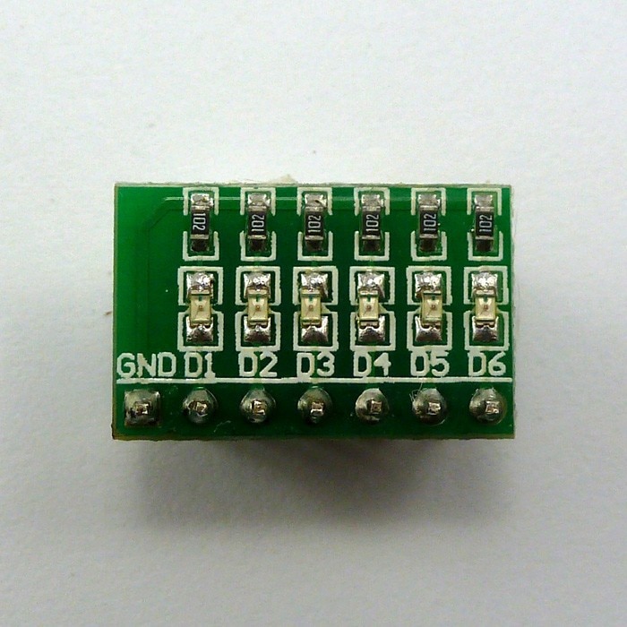
I bought these two handy things to aide with quick prototyping and troubleshooting. One is a series of LEDs and appropriate resistors mounted on PCB. The other is a similar arrangement with momentary switches. I've been using them happily for months, pushed in to a breadboard.
But earlier today I saw another use case for them: Pushed directly into the pins of an Uno.
And that made me think: Would those LEDs even work? In this photo, the GND pin of the switch module is connected to GND on the UNO. That's great. But it looks like GND of the LED module is pushed into maybe 5 or 6 of the UNO.
Hi @samshltn
Do not .
Digital or analog output pin cannot be used as GND.
For a given project it can be used with the LOW which is very close to the GND value.
If you use some digital pin like GND for these LEDs (6), the sum of the currents of these LEDs passed through only one pin and it could exceed the maximum value supported by the pin and could damage it.
Think of the pin labelled 'GND' on the LED PCB; in reality that will be the common cathode connection for all the LEDs.
An Arduino pin can be the common cathode of an LED array as long as the maximum current of the IO pin is not exceeded. This wiring is how LED matrixes work.
In practice it is possible but not recommended. However, I myself often use it when I want to try something quickly. For example, in a test with an IR receiver, I did not have enough GND pins and I programmed another free one for this purpose. When I use LEDs, I sometimes do it too, even without a current-limiting resistor, and everyone says not to do that. I am aware of the risks and I have enough spare parts, although so far I have not burned anything with this type of 'power supply'. Maybe is just luck.
Each of the outputs going to D1 to D6 is supplying 10 ma (typical current, not sure what you have).
Normally the common (aka ground) would go to the ground / common pin on the UNO which can return all the current the processor output could supply. However since you common is going to a digital pin, That pin must be commanded LOW and will take the full 60ma which is greater that its rating.
Take a look at the UNO pinouts. The LED board, at least, is designed so the GND pin will align with GND on the UNO and the LED pins can then be driven by D8-D13.
You could use the switch board with an I/O pin substituted for a GND, if you are careful to never enable the switch inputs as OUTPUT.
So just swap the position of your boards, as they are shown in your picture.
Assuming 2.5 V voltage drop on the yellow LEDs, each will draw 2.5 mA. the LEDs are highly efficient, you would not want them to be any brighter! Six of these all lit will take 15 mA. Well within the ratings of a UNO - but not necessarily some of the other variants.
So no problem at all in this particular situation. I have a couple of the eight LED multicoloured modules - but haven't done much with them and have them put away somewhere I can't find in a hurry. And I don't use UNOs much as they are so clumsy.
Applies irrespective of how you connect the common pin. In fact, connecting a HIGH and a LOW output pin is likely to cause less damage than connecting a HIGH output pin directly to ground!
That's pretty funny. It's a vendor image, not OP image that does not show the intended connection. Here is some code, direct from AliExpress to illustrate:
 /*
  Arduiuo_6led

  This example code is in the public domain.
 */

// give it a name:
int D1 = 13;
int D2 = 12;
int D3 = 11;
int D4 = 10;
int D5 = 9;
int D6 = 8;

// the setup routine runs once when you press reset:
void setup() {
  // initialize the digital pin as an output.
pinMode(D1, OUTPUT);
pinMode(D2, OUTPUT);
pinMode(D3, OUTPUT);
pinMode(D4, OUTPUT);
pinMode(D5, OUTPUT);
pinMode(D6, OUTPUT);
}
Yes, but at least if you do accidentally configure a switch input as an OUTPUT, it won't short the output until you actually push the switch (unless it's a toggle). But I guess a few seconds of futile button pushes until you see that it's not working, still has the potential to do some damage.