CAN Bus : MCP2515 with Mega Showing Configuration Mode Failure

Hello,

I need help with my CAN bus setup. I have two nodes (Arduino Uno + MCP2515) working perfectly both initialize successfully and communicate without issues.

Now I’ve added a third node using Mega + MCP2515, but the terminal keeps showing this error:

Entering Configuration Mode Failure...
Configuration Mode Failure...

the other two nodes show:

Entering Configuration Mode Successful!
Setting Baudrate Successful!
MCP2515 Initialized Successfully!

I’ve already swapped the MCP2515 module with the Uno and verified that the module itself is working fine. I am using the MCP2515 module with an onboard 8 MHz crystal. So I believe the issue could be either with the wiring or the Mega code.

I’m sharing both the code and the wiring picture for this third node below. Could you please take a look and let me know if you spot any issue?

Code

#include <SPI.h>
#include "mcp_can.h"

// CS pin for Mega is usually pin 53 (hardware SS)
#define CAN_CS_PIN 53

MCP_CAN CAN(CAN_CS_PIN);    // Set CS pin

void setup() {
  Serial.begin(9600);

  // Initialize MCP2515
  if (CAN.begin(MCP_ANY, CAN_500KBPS, MCP_8MHZ) == CAN_OK) {
    Serial.println("MCP2515 Initialized Successfully!");
  } else {
    Serial.println("Configuration Mode Failure...");
    while (1);  // Stay here if init failed
  }

  CAN.setMode(MCP_NORMAL);  // Set to normal mode
  Serial.println("CAN set to Normal Mode");
}

void loop() {
  byte data[] = {0x01, 0x02, 0x03, 0x04};
  byte sendResult = CAN.sendMsgBuf(0x100, 0, 4, data);

  if (sendResult == CAN_OK) {
    Serial.println("Message Sent Successfully");
  } else {
    Serial.println("Error Sending Message");
  }

  delay(1000);
}

@van_der_decken

Did you deactivate the termination resistor on the node in the middle?

When using more than 2 nodes in a can bus setup only the end nodes must have the termination resistor connected.

The resistor on the center nodes can be disconnected by removing the jumper.

Yes, I did deactivate the termination resistor on the middle node.

I understand that in a CAN bus setup, only the two end nodes should have the termination resistors connected, and the middle node should not.

Mega + MCP2515 is one of the end nodes in the CAN bus setup.

Hi, @adrino1

Did you try to configure the Mega with the module disconnected from the bus wires?

Can you please post your code for the UNO version and the Mega version?

Tom.... :smiley: :+1: :coffee: :australia:

I did try configuring the Mega with the module disconnected from the bus wires, but it still fails to enter Configuration Mode.

I’m sharing both the UNO version and the Mega version of the code

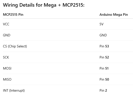
Mega Loopback test code

/* CAN Loopback Example
 * This example sends a message once a second and receives that message
 *   no CAN bus is required.  This example will test the functionality 
 *   of the protocol controller, and connections to it.
 *   
 *   Written By: Cory J. Fowler - October 5th 2016
 */

#include <mcp_can.h>
#include <SPI.h>

// CAN TX Variables
unsigned long prevTX = 0;                                        // Variable to store last execution time
const unsigned int invlTX = 1000;                                // One second interval constant
byte data[] = {0xAA, 0x55, 0x01, 0x10, 0xFF, 0x12, 0x34, 0x56};  // Generic CAN data to send

// CAN RX Variables
long unsigned int rxId;
unsigned char len;
unsigned char rxBuf[8];

// Serial Output String Buffer
char msgString[128];

// CAN0 INT and CS
#define CAN0_INT 2                              // Set INT to pin 2
MCP_CAN CAN0(53);                               // Set CS to pin 10


void setup()
{
  Serial.begin(115200);  // CAN is running at 500,000BPS; 115,200BPS is SLOW, not FAST, thus 9600 is crippling.
  
  // Initialize MCP2515 running at 16MHz with a baudrate of 500kb/s and the masks and filters disabled.
  if(CAN0.begin(MCP_ANY, CAN_500KBPS, MCP_8MHZ) == CAN_OK)
    Serial.println("MCP2515 Initialized Successfully!");
  else
    Serial.println("Error Initializing MCP2515...");
  
  // Since we do not set NORMAL mode, we are in loopback mode by default.
  //CAN0.setMode(MCP_NORMAL);

  pinMode(CAN0_INT, INPUT);                           // Configuring pin for /INT input
  
  Serial.println("MCP2515 Library Loopback Example...");
}

void loop()
{
  if(!digitalRead(CAN0_INT))                          // If CAN0_INT pin is low, read receive buffer
  {
    CAN0.readMsgBuf(&rxId, &len, rxBuf);              // Read data: len = data length, buf = data byte(s)
    
    if((rxId & 0x80000000) == 0x80000000)             // Determine if ID is standard (11 bits) or extended (29 bits)
      sprintf(msgString, "Extended ID: 0x%.8lX  DLC: %1d  Data:", (rxId & 0x1FFFFFFF), len);
    else
      sprintf(msgString, "Standard ID: 0x%.3lX       DLC: %1d  Data:", rxId, len);
  
    Serial.print(msgString);
  
    if((rxId & 0x40000000) == 0x40000000){            // Determine if message is a remote request frame.
      sprintf(msgString, " REMOTE REQUEST FRAME");
      Serial.print(msgString);
    } else {
      for(byte i = 0; i<len; i++){
        sprintf(msgString, " 0x%.2X", rxBuf[i]);
        Serial.print(msgString);
      }
    }
        
    Serial.println();
  }
  
  if(millis() - prevTX >= invlTX){                    // Send this at a one second interval. 
    prevTX = millis();
    byte sndStat = CAN0.sendMsgBuf(0x100, 8, data);
    
    if(sndStat == CAN_OK)
      Serial.println("Message Sent Successfully!");
    else
      Serial.println("Error Sending Message...");

  }
}

/*********************************************************************************************************
  END FILE
*********************************************************************************************************/

Output I checked, and the serial output only appears correctly at 9600 baud, even though the code has Serial.begin(115200);.

Entering Configuration Mode Failure...
Configuration Mode Failure...

Uno version
code

/* CAN Loopback Example
 * This example sends a message once a second and receives that message
 *   no CAN bus is required.  This example will test the functionality 
 *   of the protocol controller, and connections to it.
 *   
 *   Written By: Cory J. Fowler - October 5th 2016
 */

#include <mcp_can.h>
#include <SPI.h>

// CAN TX Variables
unsigned long prevTX = 0;                                        // Variable to store last execution time
const unsigned int invlTX = 1000;                                // One second interval constant
byte data[] = {0xAA, 0x55, 0x01, 0x10, 0xFF, 0x12, 0x34, 0x56};  // Generic CAN data to send

// CAN RX Variables
long unsigned int rxId;
unsigned char len;
unsigned char rxBuf[8];

// Serial Output String Buffer
char msgString[128];

// CAN0 INT and CS
#define CAN0_INT 2                              // Set INT to pin 2
MCP_CAN CAN0(10);                               // Set CS to pin 10


void setup()
{
  Serial.begin(115200);  // CAN is running at 500,000BPS; 115,200BPS is SLOW, not FAST, thus 9600 is crippling.
  
  // Initialize MCP2515 running at 16MHz with a baudrate of 500kb/s and the masks and filters disabled.
  if(CAN0.begin(MCP_ANY, CAN_500KBPS, MCP_8MHZ) == CAN_OK)
    Serial.println("MCP2515 Initialized Successfully!");
  else
    Serial.println("Error Initializing MCP2515...");
  
  // Since we do not set NORMAL mode, we are in loopback mode by default.
  //CAN0.setMode(MCP_NORMAL);

  pinMode(CAN0_INT, INPUT);                           // Configuring pin for /INT input
  
  Serial.println("MCP2515 Library Loopback Example...");
}

void loop()
{
  if(!digitalRead(CAN0_INT))                          // If CAN0_INT pin is low, read receive buffer
  {
    CAN0.readMsgBuf(&rxId, &len, rxBuf);              // Read data: len = data length, buf = data byte(s)
    
    if((rxId & 0x80000000) == 0x80000000)             // Determine if ID is standard (11 bits) or extended (29 bits)
      sprintf(msgString, "Extended ID: 0x%.8lX  DLC: %1d  Data:", (rxId & 0x1FFFFFFF), len);
    else
      sprintf(msgString, "Standard ID: 0x%.3lX       DLC: %1d  Data:", rxId, len);
  
    Serial.print(msgString);
  
    if((rxId & 0x40000000) == 0x40000000){            // Determine if message is a remote request frame.
      sprintf(msgString, " REMOTE REQUEST FRAME");
      Serial.print(msgString);
    } else {
      for(byte i = 0; i<len; i++){
        sprintf(msgString, " 0x%.2X", rxBuf[i]);
        Serial.print(msgString);
      }
    }
        
    Serial.println();
  }
  
  if(millis() - prevTX >= invlTX){                    // Send this at a one second interval. 
    prevTX = millis();
    byte sndStat = CAN0.sendMsgBuf(0x100, 8, data);
    
    if(sndStat == CAN_OK)
      Serial.println("Message Sent Successfully!");
    else
      Serial.println("Error Sending Message...");

  }
}

/*********************************************************************************************************
  END FILE
*********************************************************************************************************/

output

Entering Configuration Mode Successful!
Setting Baudrate Successful!
MCP2515 Initialized Successfully!
Message Sent Successfully!

That message is independent of the CAN buss but it does indicate communication problems with the MCP2515 chip. That indicates you may have a SPI configuration/connection problem. In your picture one of the (I think it is) SPI pins is not connected. The chip will initialize without a CAN buss connected but the SPI must be correct.

I’ve double-checked the wiring, and all SPI pins are properly connected between the Mega and MCP2515. Everything looks fine physically, so I’m now starting to suspect that the issue might be related to the code running on the Mega, or perhaps how the Mega handles SPI differently compared to the Uno.

Unfortunately, I don’t have a third Uno available to test this setup with the same code. If anyone can try running this code on their Mega with MCP2515 and confirm whether it initializes successfully, that would help me narrow down whether it’s a hardware specific issue or code related.

Hi, @adrino1

Do you have a Nano?

Tom.... :smiley: :+1: :coffee: :australia:

No, I don’t have a Nano. just two Unos and one Mega at the moment.

connected a Mega to a MCP2515 and communicating OK over CANbus
Mega code

// Mega MCP2515 CAN send/Receive Example 
//
// Mega <> MCP2515 connections
// MCP2515 INT to Mega  GPIO45
// MCP2515 SCK to Mega  GPIO52 CLK
// MCP2515  SI to Mega  GPIO51 MOSI
// MCP2515  SO to Mega  GPIO50 MISO
// MCP2515  CS to Mega  GPIO53  CS
// MCP2515 GND to Mega  GND
// MCP2515 VCC to Mega  5V

#include <mcp_can.h>
#include <SPI.h>

long unsigned int rxId;
unsigned char len = 0;
unsigned char rxBuf[8];
char msgString[128];  // Array to store serial string

#define CAN0_INT 45  // for Mega 
MCP_CAN CAN0(53);   // 

void setup() {
  Serial.begin(115200);
  delay(2000);
  Serial.println("\n\nMega- CAN MCP2515 shield Send/Receive test - MCP2515 Initialize");
    Serial.print("MOSI: ");
  Serial.println(MOSI);
  Serial.print("MISO: ");
  Serial.println(MISO);
  Serial.print("SCK: ");
  Serial.println(SCK);
  Serial.print("SS: ");
  Serial.println(SS);  

  // Initialize MCP2515 baudrate of 250kb/s and the masks and filters disabled.
  //  check crystal frequency!! e.g. Canbus shield is 16MHz MCP2515 is 8MHz
  if (CAN0.begin(MCP_ANY, CAN_125KBPS, MCP_8MHZ) == CAN_OK)
    Serial.println("CAN Receive - MCP2515 Initialized Successfully!");
  else
    Serial.println("Error Initializing MCP2515...");
  CAN0.setMode(MCP_NORMAL);         // Set operation mode to normal so the MCP2515 sends acks to received data.
  pinMode(CAN0_INT, INPUT_PULLUP);  // Configuring pin for /INT input *** added PULLUP ***
  Serial.println("MCP2515 Library CAN Send/Receive Example\n enter space to send a frame");
}

void loop() {
  // check for data received
  if (!digitalRead(CAN0_INT))  // If CAN0_INT pin is low, read receive buffer
  {
    CAN0.readMsgBuf(&rxId, &len, rxBuf);    // Read data: len = data length, buf = data byte(s)
    if ((rxId & 0x80000000) == 0x80000000)  // Determine if ID is standard (11 bits) or extended (29 bits)
      sprintf(msgString, "Extended ID: 0x%.8lX  DLC: %1d  Data:", (rxId & 0x1FFFFFFF), len);
    else
      sprintf(msgString, "Standard ID: 0x%.3lX       DLC: %1d  Data:", rxId, len);
    Serial.print(msgString);
    if ((rxId & 0x40000000) == 0x40000000) {  // Determine if message is a remote request frame.
      sprintf(msgString, " REMOTE REQUEST FRAME");
      Serial.print(msgString);
    } else {
      for (byte i = 0; i < len; i++) {
        sprintf(msgString, " 0x%.2X", rxBuf[i]);
        Serial.print(msgString);
      }
    }
    Serial.println();
  }
  // transmit data when space entered on keyboard
  if(Serial.available()){
    if (Serial.read() != ' ') return;
    static byte data[8] = { 0x00, 0x01, 0x02, 0x03, 0x04, 0x05, 0x06, 0x07 };
       for (byte i = 0; i < 8; i++) {
        sprintf(msgString, " 0x%.2X", data[i]);
        Serial.print(msgString);
      }
 
    // send data:  ID = 0x100, Standard CAN Frame, Data length = 8 bytes, 'data' = array of data bytes to send
    byte sndStat = CAN0.sendMsgBuf(0x100, 0, 8, data);
    if (sndStat == CAN_OK) {
      Serial.println(" Message Sent Successfully!");
    } else {
      Serial.println(" Error Sending Message...");
    }
    data[0]++;    // increment first byte of data
 }
}


Mega serial output

Mega- CAN MCP2515 shield Send/Receive test - MCP2515 Initialize
MOSI: 51
MISO: 50
SCK: 52
SS: 53
Entering Configuration Mode Successful!
Setting Baudrate Successful!
CAN Receive - MCP2515 Initialized Successfully!
MCP2515 Library CAN Send/Receive Example
 enter space to send a frame
 0x00 0x01 0x02 0x03 0x04 0x05 0x06 0x07 Message Sent Successfully!
 0x01 0x01 0x02 0x03 0x04 0x05 0x06 0x07 Message Sent Successfully!
Standard ID: 0x100       DLC: 8  Data: 0x00 0x4D 0x45 0x47 0x41 0x00 0x07 0x08
Standard ID: 0x100       DLC: 8  Data: 0x01 0x4D 0x45 0x47 0x41 0x00 0x07 0x08
Standard ID: 0x100       DLC: 8  Data: 0x00 0x00 0x00 0x00 0x00 0x00 0x00 0x00
Extended ID: 0x000FF100  DLC: 8  Data: 0x00 0x00 0x00 0x00 0x00 0x00 0x00 0x00
Standard ID: 0x100       DLC: 8  Data: 0x02 0x4D 0x45 0x47 0x41 0x00 0x07 0x08
 0x02 0x01 0x02 0x03 0x04 0x05 0x06 0x07 Message Sent Successfully!
 0x03 0x01 0x02 0x03 0x04 0x05 0x06 0x07 Message Sent Successfully!

UNO serial output

UNO CAN MCP2515 shield Send/Receive test - MCP2515 Initialize
Entering Configuration Mode Successful!
Setting Baudrate Successful!
CAN Receive - MCP2515 Initialized Successfully!
MCP2515 Library CAN Send/Receive Example
 enter space to send a frame
Standard ID: 0x100       DLC: 8  Data: 0x00 0x01 0x02 0x03 0x04 0x05 0x06 0x07
Standard ID: 0x100       DLC: 8  Data: 0x01 0x01 0x02 0x03 0x04 0x05 0x06 0x07
 0x00 0x4D 0x45 0x47 0x41 0x00 0x07 0x08 Message Sent Successfully!
 0x01 0x4D 0x45 0x47 0x41 0x00 0x07 0x08 Message Sent Successfully!
Standard ID: 0x100       DLC: 8  Data: 0x00 0x00 0x00 0x00 0x00 0x00 0x00 0x00
Extended ID: 0x000FF100  DLC: 8  Data:0x00 0x00 0x00 0x00 0x00 0x00 0x00 0x00
 0x02 0x4D 0x45 0x47 0x41 0x00 0x07 0x08 Message Sent Successfully!
Standard ID: 0x100       DLC: 8  Data: 0x02 0x01 0x02 0x03 0x04 0x05 0x06 0x07
Standard ID: 0x100       DLC: 8  Data: 0x03 0x01 0x02 0x03 0x04 0x05 0x06 0x07

also have an ESP32/TWAI, RP2040/MCP25625 and STM32/MCP2515 in CAN network

EDIT: can you run the CAN loopback test? File>Examples>mcp_can>CAN_loopback
should at least prove the Mega<>SPI communications are working

I ran the CAN_loopback example from the library. I made a few changes in the code to match my setup:

CS pin is connected to 53, so I updated the constructor accordingly.
INT pin is connected to 45
so I selected MCP_8MHZ

/* CAN Loopback Example
 * This example sends a message once a second and receives that message
 *   no CAN bus is required.  This example will test the functionality 
 *   of the protocol controller, and connections to it.
 *   
 *   Written By: Cory J. Fowler - October 5th 2016
 */

#include <mcp_can.h>
#include <SPI.h>

// CAN TX Variables
unsigned long prevTX = 0;                                        // Variable to store last execution time
const unsigned int invlTX = 1000;                                // One second interval constant
byte data[] = {0xAA, 0x55, 0x01, 0x10, 0xFF, 0x12, 0x34, 0x56};  // Generic CAN data to send

// CAN RX Variables
long unsigned int rxId;
unsigned char len;
unsigned char rxBuf[8];

// Serial Output String Buffer
char msgString[128];

// CAN0 INT and CS
#define CAN0_INT 45                              // Set INT to pin 2
MCP_CAN CAN0(53);                               // Set CS to pin 10


void setup()
{
  Serial.begin(115200);  // CAN is running at 500,000BPS; 115,200BPS is SLOW, not FAST, thus 9600 is crippling.
  
  // Initialize MCP2515 running at 16MHz with a baudrate of 500kb/s and the masks and filters disabled.
  if(CAN0.begin(MCP_ANY, CAN_500KBPS, MCP_8MHZ) == CAN_OK)
    Serial.println("MCP2515 Initialized Successfully!");
  else
    Serial.println("Error Initializing MCP2515...");
  
  // Since we do not set NORMAL mode, we are in loopback mode by default.
  //CAN0.setMode(MCP_NORMAL);

  pinMode(CAN0_INT, INPUT);                           // Configuring pin for /INT input
  
  Serial.println("MCP2515 Library Loopback Example...");
}

void loop()
{
  if(!digitalRead(CAN0_INT))                          // If CAN0_INT pin is low, read receive buffer
  {
    CAN0.readMsgBuf(&rxId, &len, rxBuf);              // Read data: len = data length, buf = data byte(s)
    
    if((rxId & 0x80000000) == 0x80000000)             // Determine if ID is standard (11 bits) or extended (29 bits)
      sprintf(msgString, "Extended ID: 0x%.8lX  DLC: %1d  Data:", (rxId & 0x1FFFFFFF), len);
    else
      sprintf(msgString, "Standard ID: 0x%.3lX       DLC: %1d  Data:", rxId, len);
  
    Serial.print(msgString);
  
    if((rxId & 0x40000000) == 0x40000000){            // Determine if message is a remote request frame.
      sprintf(msgString, " REMOTE REQUEST FRAME");
      Serial.print(msgString);
    } else {
      for(byte i = 0; i<len; i++){
        sprintf(msgString, " 0x%.2X", rxBuf[i]);
        Serial.print(msgString);
      }
    }
        
    Serial.println();
  }
  
  if(millis() - prevTX >= invlTX){                    // Send this at a one second interval. 
    prevTX = millis();
    byte sndStat = CAN0.sendMsgBuf(0x100, 8, data);
    
    if(sndStat == CAN_OK)
      Serial.println("Message Sent Successfully!");
    else
      Serial.println("Error Sending Message...");

  }
}

/*********************************************************************************************************
  END FILE
*********************************************************************************************************/

serial Output

Entering Configuration Mode Failure...
Error Initializing MCP2515...
MCP2515 Library Loopback Example...
Standard ID: 0x000       DLC: 0  Data:

I tested with another Mega board and changed the INT pin to 2—now everything works fine, and the MCP2515 initializes successfully.

So it looks like the issue was with the Mega board

code

/* CAN Loopback Example
 * This example sends a message once a second and receives that message
 *   no CAN bus is required.  This example will test the functionality 
 *   of the protocol controller, and connections to it.
 *   
 *   Written By: Cory J. Fowler - October 5th 2016
 */

#include <mcp_can.h>
#include <SPI.h>

// CAN TX Variables
unsigned long prevTX = 0;                                        // Variable to store last execution time
const unsigned int invlTX = 1000;                                // One second interval constant
byte data[] = {0xAA, 0x55, 0x01, 0x10, 0xFF, 0x12, 0x34, 0x56};  // Generic CAN data to send

// CAN RX Variables
long unsigned int rxId;
unsigned char len;
unsigned char rxBuf[8];

// Serial Output String Buffer
char msgString[128];

// CAN0 INT and CS
#define CAN0_INT 2                              // Set INT to pin 2
MCP_CAN CAN0(53);                               // Set CS to pin 10


void setup()
{
  Serial.begin(115200);  // CAN is running at 500,000BPS; 115,200BPS is SLOW, not FAST, thus 9600 is crippling.
  
  // Initialize MCP2515 running at 16MHz with a baudrate of 500kb/s and the masks and filters disabled.
  if(CAN0.begin(MCP_ANY, CAN_500KBPS, MCP_8MHZ) == CAN_OK)
    Serial.println("MCP2515 Initialized Successfully!");
  else
    Serial.println("Error Initializing MCP2515...");
  
  // Since we do not set NORMAL mode, we are in loopback mode by default.
  //CAN0.setMode(MCP_NORMAL);

  pinMode(CAN0_INT, INPUT);                           // Configuring pin for /INT input
  
  Serial.println("MCP2515 Library Loopback Example...");
}

void loop()
{
  if(!digitalRead(CAN0_INT))                          // If CAN0_INT pin is low, read receive buffer
  {
    CAN0.readMsgBuf(&rxId, &len, rxBuf);              // Read data: len = data length, buf = data byte(s)
    
    if((rxId & 0x80000000) == 0x80000000)             // Determine if ID is standard (11 bits) or extended (29 bits)
      sprintf(msgString, "Extended ID: 0x%.8lX  DLC: %1d  Data:", (rxId & 0x1FFFFFFF), len);
    else
      sprintf(msgString, "Standard ID: 0x%.3lX       DLC: %1d  Data:", rxId, len);
  
    Serial.print(msgString);
  
    if((rxId & 0x40000000) == 0x40000000){            // Determine if message is a remote request frame.
      sprintf(msgString, " REMOTE REQUEST FRAME");
      Serial.print(msgString);
    } else {
      for(byte i = 0; i<len; i++){
        sprintf(msgString, " 0x%.2X", rxBuf[i]);
        Serial.print(msgString);
      }
    }
        
    Serial.println();
  }
  
  if(millis() - prevTX >= invlTX){                    // Send this at a one second interval. 
    prevTX = millis();
    byte sndStat = CAN0.sendMsgBuf(0x100, 8, data);
    
    if(sndStat == CAN_OK)
      Serial.println("Message Sent Successfully!");
    else
      Serial.println("Error Sending Message...");

  }
}

/*********************************************************************************************************
  END FILE
*********************************************************************************************************/

Output

Message Sent Successfully!
Standard Ix56
xFF 0x12 0x34 0x56
Message Sent Successfully!
Standard ID: 0x100       DLC: 8  Data: 0xAA 0x55 0x01 0x10 0xFF 0x12 0x34 0x56
xFF 0x12 0x34 0x56
Message Sent Successfully!
Standard ID: 0x100       DLC: 8  Data: 0xAA 0x55 0x01 0x10 0xFF 0x12 0x34 0x56
Entering Configuration Mode Successful!
Setting Baudrate Successful!
MCP2515 Initialized Successfully!
MCP2515 Library Loopback Example...

you mentioned using ESP32, could you please share the code you’re using for that setup? I’d like to see how you’ve configured it

using the [Two-Wire Automotive Interface (TWAI)] interface(https://docs.espressif.com/projects/esp-idf/en/stable/esp32/api-reference/peripherals/twai.html)

// ESP32-TWAI-CAN library using a cjmcu-1051 CAN transceiver
//  adapted from  File>Examples>ESP32-TWAI-CAN>OBD2-querry

// ESP32-TWAI-CAN library
//

// cjmcu-1051 CAN transceiver wiring
//     https://www.circuitstate.com/tutorials/what-is-can-bus-how-to-use-can-interface-with-esp32-and-arduino/

// ESP32 GND    cjmcu-1051 GND
// ESP32 5V     cjmcu-1051 VCC powers transceiver
// ESP32 3.3V   cjmcu-1051 VIO powers logic
// ESP32 GPIO5  cjmcu-1051 CTX
// ESP32 GPIO4  cjmcu-1051 CRX
// ESP32 GND    cjmcu-1051 S   HIGH = TRX off, LOW = TRX on


#include <ESP32-TWAI-CAN.hpp>

// Simple sketch that transmits and receives CAN frames
// Showcasing simple use of ESP32-TWAI-CAN library driver.

// Default for ESP32
#define CAN_TX 5
#define CAN_RX 4

CanFrame rxFrame;

// transmit a test frame - either with 0's or test data
void sendObdFrame(char test) {
  static byte data = 2;  // test value - increment every frame
  CanFrame obdFrame = { 0 }, testFrame = { 0 };
  obdFrame.identifier = 0x7DF;   // Default OBD2 address;
  testFrame.identifier = 0x100;  // test OBD2 address;
  obdFrame.extd = 0;
  obdFrame.data_length_code = testFrame.data_length_code = 8;
  obdFrame.data[0] = data;
  obdFrame.data[1] = 'T';
  obdFrame.data[2] = 'W';
  obdFrame.data[3] = 'A';  // Best to use 0xAA (0b10101010) instead of 0
  obdFrame.data[4] = 'I';  // CAN works better this way as it needs
  obdFrame.data[5] = 0;    // to avoid bit-stuffing
  obdFrame.data[6] = 0xAA;
  obdFrame.data[7] = 0xAA;
  if (test == ' ') {
    ESP32Can.writeFrame(testFrame);  // timeout defaults to 1 ms
    Serial.printf("Transmit frame: %03X: ", testFrame.identifier);
    for (byte i = 0; i < 8; i++)
      Serial.printf(" 0x%.2X", testFrame.data[i]);
  } else {
    // Accepts both pointers and references
    ESP32Can.writeFrame(obdFrame);  // timeout defaults to 1 ms
    data++;                         // increment for testing
    Serial.printf("Transmit frame: %03X: ", obdFrame.identifier);
    for (byte i = 0; i < 8; i++)
      Serial.printf(" 0x%.2X", obdFrame.data[i]);
  }
  Serial.printf("\n");
}

void setup() {
  // Setup serial for debbuging.
  Serial.begin(115200);
  delay(3000);
  Serial.println("\n\nESP32-TWAI-CAN Send/Receive test -  Initialize");
  // Set pins
  ESP32Can.setPins(CAN_TX, CAN_RX);
  // You can set custom size for the queues - those are default
  ESP32Can.setRxQueueSize(5);
  ESP32Can.setTxQueueSize(5);
  // .setSpeed() and .begin() functions require to use TwaiSpeed enum,
  // but you can easily convert it from numerical value using .convertSpeed()
  /*ESP32Can.setSpeed(ESP32Can.convertSpeed(250));  //500));
  // You can also just use .begin()..
  if (ESP32Can.begin()) {
    Serial.println("CAN bus started!");
  } else {
    Serial.println("CAN bus failed!");
  }*/
  // or override everything in one command;
  // It is also safe to use .begin() without .end() as it calls it internally
  if (ESP32Can.begin(ESP32Can.convertSpeed(125), CAN_TX, CAN_RX, 10, 10)) {
    Serial.println("CAN bus started!");
  } else {
    Serial.println("CAN bus failed!");
  }
}

void loop() {
  // transmit data when key entered on keyboard
  if (Serial.available()) {
    sendObdFrame(Serial.read());  // For coolant temperature
    while (Serial.available()) Serial.read();
  }

  // frame received?  You can set custom timeout, default is 1000
  if (ESP32Can.readFrame(rxFrame, 100)) {
    // print frame contents
    Serial.printf("Received frame: %03X: ", rxFrame.identifier);
    for (byte i = 0; i < 8; i++)
      Serial.printf(" 0x%.2X", rxFrame.data[i]);
    Serial.printf(" %s\n", (char *)&rxFrame.data + 1);
  }
}

current test setup