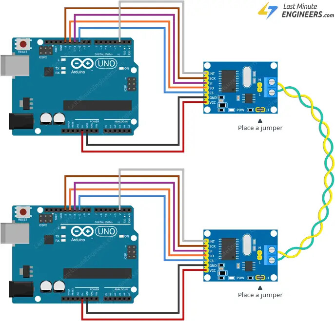
I’m using two MCP2515 CAN modules with Arduino, following this tutorial . I’ve set up a sender and receiver node, but the sender shows the error:
CAN Sender
Starting CAN failed!
I’ve double-checked the SPI connections (MISO, MOSI, SCK, CS) between the MCP2515 and the Arduino. I’ve also ensured the CAN_H and CAN_L lines are connected between the two modules. I’ve placed jumper on both boards as the tutorial suggested (since there are only two modules in the network).
Your problem is not unexpected, and your wiring may be the root cause. Since hardware and design is involved, it’s crucial to provide an accurate, annotated schematic of your circuit as it is currently wired. Please note that Fritzing diagrams are not considered proper schematics; they are wiring diagrams and are often not helpful for troubleshooting. I use Cory Fowler's MCP_CAN library. It has both transmit and receive sketches included. GitHub - coryjfowler/MCP_CAN_lib: MCP_CAN Library
What to Include:
Annotated Schematic: Show all connections, including power, ground, and power sources. This helps us understand how your circuit is set up and identify any potential issues.
Technical Information Links: Provide links to technical documentation for each hardware device used in your setup. Avoid links to sales sites like Amazon, as they usually lack the necessary technical details. We need complete specifications to help you effectively.
Additional Information Needed: If the above details are incorrect, more information is required. Tell us what hardware and software you are using, the format of any data (like map data), and how your system determines its position. For example, if your project involves a robot, describe how it navigates and what computers are involved.
Bill of Materials:
5.A schematic provides a visual representation of the electrical connections and components in a circuit, showing how they interact and function together, while a Bill of Materials (BOM) is simply a list of components with part numbers and quantities needed for assembly. Unlike a BOM, a schematic illustrates the design’s logic and allows for troubleshooting and understanding circuit behavior. A BOM is useful for sourcing parts but doesn’t convey how they connect or operate in the circuit, which is critical information for understanding and working with electronics.
Why This Matters:
We have no way of knowing the specifics of your setup unless you provide that information. Clear and detailed descriptions enable us to offer the most accurate help possible. Without these details, it’s difficult to diagnose and solve the issues you're experiencing.
We need the following:
Annotated Schematic: Clearly show all connections, including power, ground, and power sources. This will help us understand your circuit setup and identify potential issues.
Technical Information Links: Provide links to technical documentation for each hardware component in your setup. Avoid links to sales sites like Amazon, as they often lack the detailed specifications we need to assist you effectively.
Give yourself an early Christmas present and pick up these resources, along with the Arduino Cookbook:
#include <CAN.h>

void setup() {
  Serial.begin(9600);
  while (!Serial);

  Serial.println("CAN Sender");

  // start the CAN bus at 500 kbps
  if (!CAN.begin(500E3)) {
    Serial.println("Starting CAN failed!");
    while (1);
  }
}

void loop() {
  // send packet: id is 11 bits, packet can contain up to 8 bytes of data
  Serial.print("Sending packet ... ");

  CAN.beginPacket(0x12);
  CAN.write('h');
  CAN.write('e');
  CAN.write('l');
  CAN.write('l');
  CAN.write('o');
  CAN.endPacket();

  Serial.println("done");

  delay(1000);

  // send extended packet: id is 29 bits, packet can contain up to 8 bytes of data
  Serial.print("Sending extended packet ... ");

  CAN.beginExtendedPacket(0xabcdef);
  CAN.write('w');
  CAN.write('o');
  CAN.write('r');
  CAN.write('l');
  CAN.write('d');
  CAN.endPacket();

  Serial.println("done");

  delay(1000);
}
Program for receiver node
#include <CAN.h>

void setup() {
  Serial.begin(9600);
  while (!Serial);

  Serial.println("CAN Receiver Callback");

  // start the CAN bus at 500 kbps
  if (!CAN.begin(500E3)) {
    Serial.println("Starting CAN failed!");
    while (1);
  }

  // register the receive callback
  CAN.onReceive(onReceive);
}

void loop() {
  // do nothing
}

void onReceive(int packetSize) {
  // received a packet
  Serial.print("Received ");

  if (CAN.packetExtended()) {
    Serial.print("extended ");
  }

  if (CAN.packetRtr()) {
    // Remote transmission request, packet contains no data
    Serial.print("RTR ");
  }

  Serial.print("packet with id 0x");
  Serial.print(CAN.packetId(), HEX);

  if (CAN.packetRtr()) {
    Serial.print(" and requested length ");
    Serial.println(CAN.packetDlc());
  } else {
    Serial.print(" and length ");
    Serial.println(packetSize);

    // only print packet data for non-RTR packets
    while (CAN.available()) {
      Serial.print((char)CAN.read());
    }
    Serial.println();
  }

  Serial.println();
}
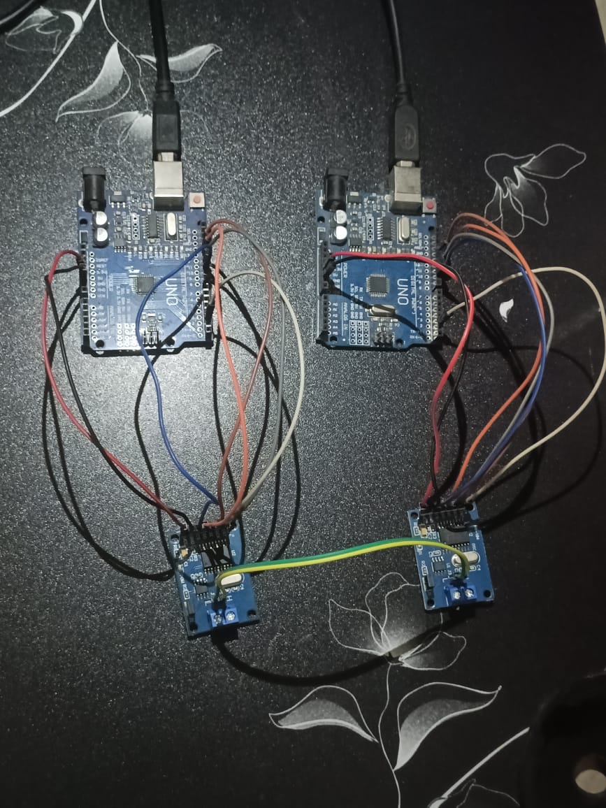
If you still want me to draw a detailed schematic diagram, I can create one on paper and share it for further clarification. Please let me know!
That would be great. From your photos I suggest a longer piece of wire for the CAN bus. The lettering is fuzzy on my side. In the top picture it appears the CAN H/L are crossed, ok in the bottom.
I’ve switched to Cory Fowler’s MCP_CAN library as you recommended.
From my observations, it seems the sender is successfully sending messages, but the receiver is showing errors. I’ve attached screenshots of the error messages for both the sender and receiver for your reference.
// CAN Send Example
//

#include <mcp_can.h>
#include <SPI.h>

MCP_CAN CAN0(10);     // Set CS to pin 10

void setup()
{
  Serial.begin(115200);

  // Initialize MCP2515 running at 16MHz with a baudrate of 500kb/s and the masks and filters disabled.
  if(CAN0.begin(MCP_ANY, CAN_500KBPS, MCP_16MHZ) == CAN_OK) Serial.println("MCP2515 Initialized Successfully!");
  else Serial.println("Error Initializing MCP2515...");

  CAN0.setMode(MCP_NORMAL);   // Change to normal mode to allow messages to be transmitted
}

byte data[8] = {0x00, 0x01, 0x02, 0x03, 0x04, 0x05, 0x06, 0x07};

void loop()
{
  // send data:  ID = 0x100, Standard CAN Frame, Data length = 8 bytes, 'data' = array of data bytes to send
  byte sndStat = CAN0.sendMsgBuf(0x100, 0, 8, data);
  if(sndStat == CAN_OK){
    Serial.println("Message Sent Successfully!");
  } else {
    Serial.println("Error Sending Message...");
  }
  delay(100);   // send data per 100ms
}

/*********************************************************************************************************
  END FILE
*********************************************************************************************************/
receiver code
// CAN Receive Example
//

#include <mcp_can.h>
#include <SPI.h>

long unsigned int rxId;
unsigned char len = 0;
unsigned char rxBuf[8];
char msgString[128];                        // Array to store serial string

#define CAN0_INT 2                              // Set INT to pin 2
MCP_CAN CAN0(10);                               // Set CS to pin 10


void setup()
{
  Serial.begin(115200);

  // Initialize MCP2515 running at 16MHz with a baudrate of 500kb/s and the masks and filters disabled.
  if(CAN0.begin(MCP_ANY, CAN_500KBPS, MCP_16MHZ) == CAN_OK)
    Serial.println("MCP2515 Initialized Successfully!");
  else
    Serial.println("Error Initializing MCP2515...");

  CAN0.setMode(MCP_NORMAL);                     // Set operation mode to normal so the MCP2515 sends acks to received data.

  pinMode(CAN0_INT, INPUT);                            // Configuring pin for /INT input

  Serial.println("MCP2515 Library Receive Example...");
}

void loop()
{
  if(!digitalRead(CAN0_INT))                         // If CAN0_INT pin is low, read receive buffer
  {
    CAN0.readMsgBuf(&rxId, &len, rxBuf);      // Read data: len = data length, buf = data byte(s)

    if((rxId & 0x80000000) == 0x80000000)     // Determine if ID is standard (11 bits) or extended (29 bits)
      sprintf(msgString, "Extended ID: 0x%.8lX  DLC: %1d  Data:", (rxId & 0x1FFFFFFF), len);
    else
      sprintf(msgString, "Standard ID: 0x%.3lX       DLC: %1d  Data:", rxId, len);

    Serial.print(msgString);

    if((rxId & 0x40000000) == 0x40000000){    // Determine if message is a remote request frame.
      sprintf(msgString, " REMOTE REQUEST FRAME");
      Serial.print(msgString);
    } else {
      for(byte i = 0; i<len; i++){
        sprintf(msgString, " 0x%.2X", rxBuf[i]);
        Serial.print(msgString);
      }
    }

    Serial.println();
  }
}

/*********************************************************************************************************
  END FILE
*********************************************************************************************************/
I cannot clearly read your screenshots, but I’m assuming there are no errors during initialization and that the system starts correctly.
Looking at the protocol, the sender requires an acknowledgment from a device on the bus. Without this acknowledgment, an error will occur.
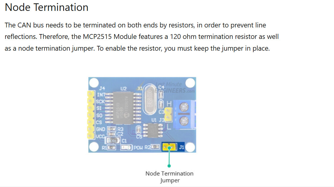
What value of termination resistors are you using on the bus? With the power off, measure the resistance between CAN_H and CAN_L. It should be approximately 60 ohms. If this value is incorrect, the CAN bus will not function properly.
The bus should measure around 60 ohms. At approximately 120 ohms, it might work under ideal conditions, but it's unreliable. You need two termination resistors, one at each physical end of the bus. Having only one or none, as you're discovering, leads to significant issues.
Yes, I have swapped the CAN modules between the Arduino boards, but I still encounter the same issue as before. This makes me think the problem might not be with a specific module
I currently have two nodes, and each module has a 120-ohm termination resistor. Could you help me understand why the bus should measure 60 ohms in this case?