Mcp-can bus receiver getting garbage data

Hi all,

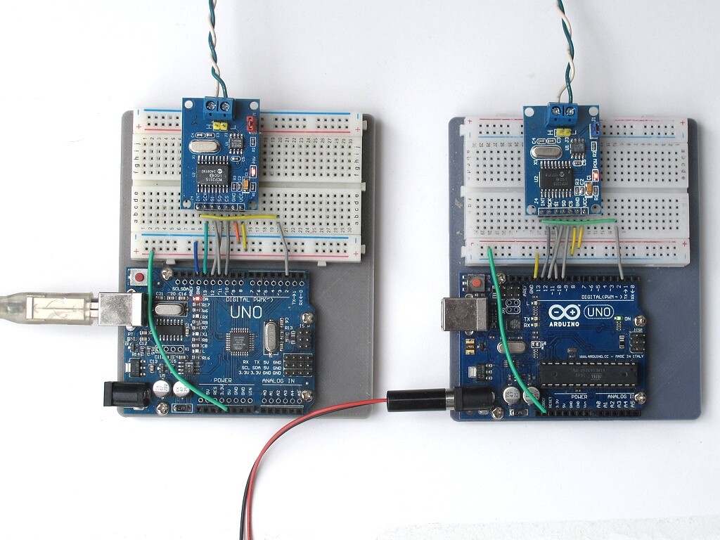
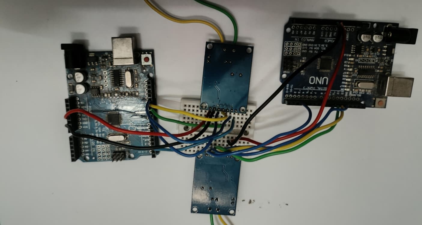
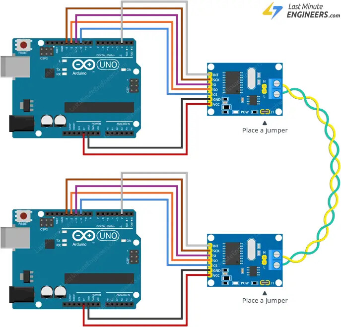
I'm working with two MCP2515 CAN modules connected to Arduino Uno boards one as sender, one as receiver. Wiring is okay — MISO, MOSI, SCK, CS, are properly connected. CANH and CANL are linked between both modules, with 120Ω termination resistors at each end. Ground is shared. I'm using the "send" and "receive" example codes from the mcp_can library.
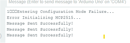
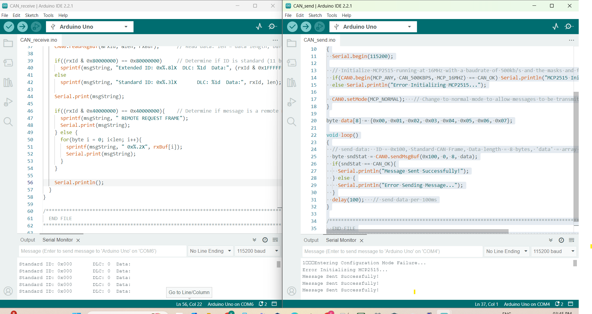
The sender shows:

The sender shows:

Message Sent Successfully!

But the receiver continuously shows:

Standard ID: 0x000 DLC: 0 Data:

Even though I expect messages with ID 0x100 and 8 bytes of data.

While debugging, I noticed the following line in both sender and receiver code:

CAN0.begin(MCP_ANY, CAN_500KBPS, MCP_16MHZ);

However, on inspecting the MCP2515 module, I realized the crystal oscillator is actually 8 MHz, not 16 MHz. so I changed it to:

CAN0.begin(MCP_ANY, CAN_500KBPS, MCP_8MHZ);

but I still get ID: 0x000 with zero-length data on the receiver.

sender code

// CAN Send Example
//

#include <mcp_can.h>
#include <SPI.h>

MCP_CAN CAN0(10);     // Set CS to pin 10

void setup()
{
  Serial.begin(115200);

  // Initialize MCP2515 running at 16MHz with a baudrate of 500kb/s and the masks and filters disabled.
  if(CAN0.begin(MCP_ANY, CAN_500KBPS, MCP_8MHZ) == CAN_OK) Serial.println("MCP2515 Initialized Successfully!");
  else Serial.println("Error Initializing MCP2515...");

  CAN0.setMode(MCP_NORMAL);   // Change to normal mode to allow messages to be transmitted
}

byte data[8] = {0x00, 0x01, 0x02, 0x03, 0x04, 0x05, 0x06, 0x07};

void loop()
{
  // send data:  ID = 0x100, Standard CAN Frame, Data length = 8 bytes, 'data' = array of data bytes to send
  byte sndStat = CAN0.sendMsgBuf(0x100, 0, 8, data);
  if(sndStat == CAN_OK){
    Serial.println("Message Sent Successfully!");
  } else {
    Serial.println("Error Sending Message...");
  }
  delay(100);   // send data per 100ms
}

/*********************************************************************************************************
  END FILE
*********************************************************************************************************/

Receiver code

// CAN Receive Example
//

#include <mcp_can.h>
#include <SPI.h>

long unsigned int rxId;
unsigned char len = 0;
unsigned char rxBuf[8];
char msgString[128];                        // Array to store serial string

#define CAN0_INT 2                              // Set INT to pin 2
MCP_CAN CAN0(10);                               // Set CS to pin 10


void setup()
{
  Serial.begin(115200);
  
  // Initialize MCP2515 running at 16MHz with a baudrate of 500kb/s and the masks and filters disabled.
  if(CAN0.begin(MCP_ANY, CAN_500KBPS, MCP_8MHZ) == CAN_OK)
    Serial.println("MCP2515 Initialized Successfully!");
  else
    Serial.println("Error Initializing MCP2515...");
  
  CAN0.setMode(MCP_NORMAL);                     // Set operation mode to normal so the MCP2515 sends acks to received data.

  pinMode(CAN0_INT, INPUT);                            // Configuring pin for /INT input
  
  Serial.println("MCP2515 Library Receive Example...");
}

void loop()
{
  if(!digitalRead(CAN0_INT))                         // If CAN0_INT pin is low, read receive buffer
  {
    CAN0.readMsgBuf(&rxId, &len, rxBuf);      // Read data: len = data length, buf = data byte(s)
    
    if((rxId & 0x80000000) == 0x80000000)     // Determine if ID is standard (11 bits) or extended (29 bits)
      sprintf(msgString, "Extended ID: 0x%.8lX  DLC: %1d  Data:", (rxId & 0x1FFFFFFF), len);
    else
      sprintf(msgString, "Standard ID: 0x%.3lX       DLC: %1d  Data:", rxId, len);
  
    Serial.print(msgString);
  
    if((rxId & 0x40000000) == 0x40000000){    // Determine if message is a remote request frame.
      sprintf(msgString, " REMOTE REQUEST FRAME");
      Serial.print(msgString);
    } else {
      for(byte i = 0; i<len; i++){
        sprintf(msgString, " 0x%.2X", rxBuf[i]);
        Serial.print(msgString);
      }
    }
        
    Serial.println();
  }
}

/*********************************************************************************************************
  END FILE
*********************************************************************************************************/

I'm attaching a snapshot of the receiver’s serial output below.

When I connect int pin receiver show

your transmitter reports
image

looks as if it has not initialized correctly - check your wiring?

avoid posting images of text? they waste space and the text cannot be copied
copy the text and paste using code tags < CODE/ >

Thanks for the suggestion. The sender’s serial output shows “Message Sent Successfully!”, This confirms that sender sending CAN messages.

I'm pretty sure there’s no wiring issue, I've already tested and verified the connections multiple times.

To be sure, I even swapped the MCP2515 modules between the sender and receiver, and tested all four combinations (both modules as sender and receiver). In every case, the receiver still shows the same issue, empty messages with ID 0x000 and DLC: 0.

Sorry about posting images I’m new here I’ll use code tags next time. Thanks for pointing it out

if the device has not initialized correctly the success messages may well be meaningless - in general on initialization failure I would not then attempt to use a device

try reducing the CAN baudrate to 125K?

do you have an oscilloscope or logic analyzer to examine the H and L signals?

I find a USB-CAN module to plug into a PC is useful for monitoring the canbus

possibly change the post title to "mcp-can bus receiver getting garbage data" so it is clear the mcp-can library is being used

Yes, I have a logic analyzer and I’ve captured the CAN_H and CAN_L waveforms and I am sharing with you

If you get this message the module is connected correctly. Your picture is useless, it is always better to show what you actually have, preferably with an annotated schematic or clear pictures.

I am assuming the code is the examples included with the library with only the xtl modification.

What you found on the crystal is a common problem and your change in code will fix it. If you did not make that change it would still work but at 250KBS, the MCP2515 is a stable part.

The library is good, I have used it many times without ever encountering a problem.

Is your buss at least a meter or more in length, if not extend it a bit. Is it a twisted pair (preferred but not mandatory)?

How is the buss terminated, with the power off it should measure about 60 Ohms.

in the screen images in post 1 the receiver appears to initialize Ok but the transmitter fails with error message
image

but then goes on the print that messages are sent successfully

initialization failure generally indicates something is wrong and I would not attempt to use a device

have you tested the modules using the MCP2515_CAN loopback example File>Examples>mcp_can>CAN_loopback

I’ve tried with two UNO boards, two Mega boards, and three different MCP2515 modules, and in several cases, when I get “Initialization Failed”, the sketch still prints “Message Sent Successfully!”

It’s strange behavior, especially since I'd expect message sending to be blocked if initialization failed. Do you think it's a bug in the library or just misleading print logic?

is there anything else connected to the UNOs?

have you tested the modules using the MCP2515_CAN loopback example File>Examples>mcp_can>CAN_loopback

that checks the SPI connection etc is operating OK

I connected one UNO with an MCP2515 module and uploaded the loopback sketch. Even though it printed “Initialization Failed,” it still went on to say “Message Sent Successfully!” which doesn't make sense. If the init really failed, how is it still sending? Makes me think the code might be printing that without actually checking the result properly.

I tried the same with a Mega and another MCP2515, and saw the same behavior.

In fact, I’ve tried so many combinations, swapping boards, modules, and wiring and I still get the same behavior. So it really feels like the example code is just printing that message without properly checking if the message was actually sent.

An old saying "It takes two tango!" CAN requires at least one transmitter and receiver to be operational before it can communicate. Please answer the previous questions and post an annotated schematic showing exactly how you have wired this and if possible a clear photo of the transmitter and receiver units.

I’m not sure what’s unclear in the image I shared earlier that wiring setup is actually taken directly from the tutorial on this site: [ https://lastminuteengineers.com/mcp2515-can-module-arduino-tutorial/ ]. I followed the exact same connection as shown there, including placing the jumper on both MCP2515 modules for 120Ω termination. My own setup is hard to photograph clearly because of all the jumper wires, but the one from the site represents exactly how I’ve wired mine. Please take a look at that it’s the same I’ve used.

That tells me what you think you have not what you have. Try close up photos of each of the modules. If the wires are as bad as you say they are that may be your problem.

1 Like

That may be what you thought you did. But it may not be what you actually did.

I just loaded your sender and receiver sketches into 2 Uno R3s with MCP2515 CAN modules wired up as shown in the Last Minute Engineers picture. Here is a photo of my actual setup.

And here are the actual sketches I used, so you can verify that there are no changes between what I loaded and what you did.

Sender

// CAN Send Example
//

#include <mcp_can.h>
#include <SPI.h>

MCP_CAN CAN0(10);     // Set CS to pin 10

void setup()
{
  Serial.begin(115200);

  // Initialize MCP2515 running at 16MHz with a baudrate of 500kb/s and the masks and filters disabled.
  if(CAN0.begin(MCP_ANY, CAN_500KBPS, MCP_8MHZ) == CAN_OK) Serial.println("MCP2515 Initialized Successfully!");
  else Serial.println("Error Initializing MCP2515...");

  CAN0.setMode(MCP_NORMAL);   // Change to normal mode to allow messages to be transmitted
}

byte data[8] = {0x00, 0x01, 0x02, 0x03, 0x04, 0x05, 0x06, 0x07};

void loop()
{
  // send data:  ID = 0x100, Standard CAN Frame, Data length = 8 bytes, 'data' = array of data bytes to send
  byte sndStat = CAN0.sendMsgBuf(0x100, 0, 8, data);
  if(sndStat == CAN_OK){
    Serial.println("Message Sent Successfully!");
  } else {
    Serial.println("Error Sending Message...");
  }
  delay(100);   // send data per 100ms
}

/*********************************************************************************************************
  END FILE
*********************************************************************************************************/

Receiver

// CAN Receive Example
//

#include <mcp_can.h>
#include <SPI.h>

long unsigned int rxId;
unsigned char len = 0;
unsigned char rxBuf[8];
char msgString[128];                        // Array to store serial string

#define CAN0_INT 2                              // Set INT to pin 2
MCP_CAN CAN0(10);                               // Set CS to pin 10


void setup()
{
  Serial.begin(115200);
  
  // Initialize MCP2515 running at 16MHz with a baudrate of 500kb/s and the masks and filters disabled.
  if(CAN0.begin(MCP_ANY, CAN_500KBPS, MCP_8MHZ) == CAN_OK)
    Serial.println("MCP2515 Initialized Successfully!");
  else
    Serial.println("Error Initializing MCP2515...");
  
  CAN0.setMode(MCP_NORMAL);                     // Set operation mode to normal so the MCP2515 sends acks to received data.

  pinMode(CAN0_INT, INPUT);                            // Configuring pin for /INT input
  
  Serial.println("MCP2515 Library Receive Example...");
}

void loop()
{
  if(!digitalRead(CAN0_INT))                         // If CAN0_INT pin is low, read receive buffer
  {
    CAN0.readMsgBuf(&rxId, &len, rxBuf);      // Read data: len = data length, buf = data byte(s)
    
    if((rxId & 0x80000000) == 0x80000000)     // Determine if ID is standard (11 bits) or extended (29 bits)
      sprintf(msgString, "Extended ID: 0x%.8lX  DLC: %1d  Data:", (rxId & 0x1FFFFFFF), len);
    else
      sprintf(msgString, "Standard ID: 0x%.3lX       DLC: %1d  Data:", rxId, len);
  
    Serial.print(msgString);
  
    if((rxId & 0x40000000) == 0x40000000){    // Determine if message is a remote request frame.
      sprintf(msgString, " REMOTE REQUEST FRAME");
      Serial.print(msgString);
    } else {
      for(byte i = 0; i<len; i++){
        sprintf(msgString, " 0x%.2X", rxBuf[i]);
        Serial.print(msgString);
      }
    }
        
    Serial.println();
  }
}

/*********************************************************************************************************
  END FILE
*********************************************************************************************************/

Connected the receiver up to my PC, started up a terminal program and applied power.

And it worked like a charm.

Welcome to minicom 2.8

OPTIONS: I18n 
Port /dev/ttyUSB0, 10:41:32

Press CTRL-] Z for help on special keys

Entering Configuration Mode Successful!
Setting Baudrate Successful!
MCP2515 Initialized Successfully!
MCP2515 Library Receive Example...
Standard ID: 0x100       DLC: 8  Data: 0x00 0x01 0x02 0x03 0x04 0x05 0x06 0x07
.
.
.

So what can we conclude?

One conclusion would be that your setup does not match what the Last Minute Engineers picture shows. Why? Because my setup did, and it worked. Therefore, there must be something different in your setup. Either your wiring is incorrect, or you have a bad module. A photo of your actual wiring would allow eliminating one possibility. That's why you're being asked to show it.

This is all to say, this is why you don't show what someone else has done that works when what you have done doesn't work.

1 Like

Take a close look at the crystals, one appears to be a 16Mhz the other 8Mhz. If thyat is correct adjust your code and it should work.

Thanks to all of you, really appreciate the support and patience until the problem got solved

So I think we can finally conclude the problem was with the bad quality of jumper wires. I removed all the connections and placed the MCP2515 modules on a breadboard. Then I connected the UNO and MCP using solid core wires. After that, I uploaded the sender sketch to one UNO and the receiver sketch to the other, and now I believe I’m finally getting the expected output on both ends.

Sender output

?��Entering Configuration Mode Successful!
Setting Baudrate Successful!
MCP2515 Initialized Successfully!
Message Sent Successfully!

Receiver output

Entering Configuration Mode Successful!
Setting Baudrate Successful!
MCP2515 Initialized Successfully!
MCP2515 Library Receive Example...
Standard ID: 0x100       DLC: 8  Data: 0x00 0x01 0x02 0x03 0x04 0x05 0x06 0x07

I’m attaching a snap of my setup too. I know it’s a bit messy and hard to follow . The header pins on my modules are facing upward, so you can’t really see the labels on the MCP2515 itself.