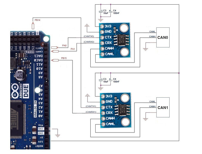
Thank you @Klaus_K that makes a lot of sense now. I've taken the drawing example that @ard_newbie posted above and modified it with the can transceiver boards that i purchased and rubbed out the 120ohm resistors. Can you kindly have a look at the drawing and tell me if that looks right? I think I will get some 10uF and 100nF ceramic capacitors and put them if that is the safer and better option. So the 100nF capacitor goes before the 10uF capacitor on the board end?
The 3.3V output goes from the DUE board. What pin does the DUE board get its power from? Is it only from the micro USB? isn't micro-usb for programming it? Does all the ground connections come from the same ground connection that will power the DUE?

