

Can I combine npk soil sensor with Heltec LoRa 32 V3, using rs485??
you can try connecting the ESP32S3 Serial1 hardware port to a RS485 module
e.g. a simple test of Serial1 using GPIO pins 6 and 7
// //  TTGO Lora OLED V3 - use "Heltec WiFio LoTa 32(V3)"   Serial1 test
// - for loopback test connect pin U1TXD to pin U1RXD"
// ss https://docs.espressif.com/projects/esp-idf/en/latest/esp32s3/_images/ESP32-S3_DevKitC-1_pinlayout_v1.1.jpg

#define RXD1 6
#define TXD1 7

void setup() {
  // initialize both serial ports:
  Serial.begin(115200);
  Serial1.begin(9600, SERIAL_8N1, RXD1, TXD1);
  Serial.println();
  Serial.println("\n\nESP32-S3 TTGO Lora OLED V3 serial1  test pin GPIO17 U1TXD pin GPIO18 U1RXD");
  Serial.write("   for loopback test connect pin GPIO17 U1TXD to pin GPIO18 U1RXD\n");
  Serial.printf("RS232: ESP32S3 pin %d RXD1 to TTL/RS232 Rx and pin %d TXD1 to TTL/RS232 Tx\n", RXD1, TXD1);
  Serial.printf("RS232 - loopback connect 9-pin D-type pin 2 Tx to pin 3 Rx\n");
}

void loop() {
  // read from port 1, send to port 0:
  if (Serial1.available()) {
    int inByte = Serial1.read();
    Serial.write(inByte);
  }

  // read from port 0, send to port 1:
  if (Serial.available()) {
    int inByte = Serial.read();
    //Serial.write(inByte);
    Serial1.write(inByte);
  }
}
serial monitor output (GPIO6 connected to GPIO7)
ESP32-S3 TTGO Lora OLED V3 serial1  test pin GPIO17 U1TXD pin GPIO18 U1RXD
   for loopback test connect pin GPIO17 U1TXD to pin GPIO18 U1RXD
RS232: ESP32S3 pin 6 RXD1 to TTL/RS232 Rx and pin 7 TXD1 to TTL/RS232 Tx
RS232 - loopback connect 9-pin D-type pin 2 Tx to pin 3 Rx
loopback test1
test2 1234567890
test3 abcdefghijklmnopqrstuvwxyz
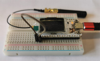
photo
I find it a good idea to have a USB-RS485 module to display traffic on a PC - I tend to use a FTDI RS485 module but there are lower cost modules on EBAY
do you know the protocol used by the soil sensor?
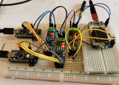
connected Heltec V3 to a couple of Nanos via RS485 (see httphow-to-interface-arduino-with-rs485-modbus-protocol-using-max485-module for details of RS485 module)
//  TTGO ESP32S3 Lora OLED V3 - use "Heltec WiFio LoTa 32(V3)"

#define RXD1 6   //  ESP32 Serial1 Receive  pin 6 to RO
#define TXD1 7   //  ESP32 Serial1 Transmit pin 7 to DI
#define SSerialTxControl 5  //RS485 Direction control DE & RE jumpered together

#define RS485Transmit HIGH
#define RS485Receive LOW

void setup()
{
  delay(1000);
  Serial.begin(115200);
  Serial.println("\n\nTTGO ESP32S3 V3 to RS485 - Use Serial Monitor, type in upper window, ENTER");
  Serial.println("Use Serial Monitor, type in upper window, ENTER");
  Serial1.begin(9600, SERIAL_8N1, RXD1, TXD1);
  pinMode(SSerialTxControl, OUTPUT);
  digitalWrite(SSerialTxControl, RS485Receive);  // Init Transceiver
}

void loop() {
  if (Serial.available()) {
    char byteReceived = Serial.read();
    digitalWrite(SSerialTxControl, RS485Transmit);  // Enable RS485 Transmit
    Serial1.write(byteReceived);                // Send byte to Remote Arduino
    Serial1.flush();
    digitalWrite(SSerialTxControl, RS485Receive);  // Disable RS485 Transmit
  }
  if (Serial1.available())  //Look for data from, RS485
  {
    char byteReceived = Serial1.read();  // Read received byte
    Serial.write(byteReceived);              // Show on Serial Monitor
  }
}
Heltec output
TTGO ESP32S3 V3 to RS485 - Use Serial Monitor, type in upper window, ENTER
Use Serial Monitor, type in upper window, ENTER
hello from Nano
test2 from nano 1234567890
test 3 froim nano abcdefghijklmnopqrstuvwxyz
nano output
Nano to RS485 - Use Serial Monitor, type in upper window, ENTER
Use Serial Monitor, type in upper window, ENTER
hello from TTGO V3
test 2 from TTGO V3 12234567890
test 3 from TTGO V3 abcdefghijklmnopqrstuvwxyz
test setup
the protocol used is Modbus-RTU