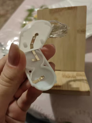
I'd like to use these Fairy lights powered by 2 CR2032 batteries as a sunrise light alarm / dimmable nightstand lamp.
My plan is to cut the wires so the LEDs are split from the battery box, then connect everything back to the Arduino with some potentiometer and transistor in between.
Is it something reasonable?
What would be the safety considerations?
Some stuff I'm thinking:
Use gloves
Cut wire with cable cutter
Strip the wire with wire stripper
Heat shrink for the stripped wires
Terminal block to keep everything tight and extra safety.
From what I can see, these are just lights and a 3V power supply. Replacing the two coin cell power supply with an Arduino PWM (for on/off and dimming) pin controlling a MOSFET should work. Finding a 3.3V MOSFET will be a challenge but doable.
Hey thanks @sonofcy ! I also thought about using the Arduino PWM directly but I saw this reddit post saying that an Arduino pin can only supply 40mA max, so it would not be enough to light up the 20 LEDs?
I'm thinking you can prolly get away using bare hands, unless you meant avoiding cutting yourself with the wire cutters or burning yourself with the soldering iron.
Both of which you can easily avoid or will quickly learn how not to do.
Doesn't really matter, as long as it can measure 6V or more.
Before you cut the wires, make a long mark with a pen or marker on one of the wires. Make sure the batteries are removed before you cut the wires. Cut the wires so that you can see the mark on both sides of the cut.
Strip the wires on the battery pack, put in the batteries and measure the voltage between the two wires. One way it will be positive and the other will be negative. When you measure positive then the wire that is connected to the meter positive lead will be the LED positive side. Just note if it's the marked or un-marked wire.
After you find which is the positive, connect one end of a 220Ω resistor to the positive wire and the other end of the resistor to any Arduino pin. Connect the other wire to the Arduino GND.
Correct. A constant source of frustration here is teaching new folks that an MPU or MCU can not power loads much bigger than a temperature or humidity sensor. I don't know the specs on those tiny LEDs but anything more than about two mA times 20 will be too much.
My guess is that there are a few leds in series.
Otherwise 6V is not very efficient...
20 leds in parallel may very well destruct the pin...
Unless you add 3kohm resistors and accept very dim leds. Which may be fine as it is a mood light.
Strings of 10 will be 0.166 amps or 0.0166 amps per LED, a plausible 17 mA.
I don't like coin cells supplying 0.166 amps, all the specifications are highly dubious especially considering they packing the sam thing in longer strings.