Can I get some feedback on the following circuit?

Hi, I recently connected this circuit to a Arduino Pro Mini, and the thing died after about of minute of activating the motor. (Picture shows uno, but I assume you can just replace VIN with RAW, and 5V with VCC, you get the same outcome?)

The thing is, the soldering job was atrocious, so I'm not sure if this circuit is dangerous for a Pro mini, or if I created a short circuit in my wiring work. The only thing I can guess is adding some kind of resistor between pin 3 and the mosfet?

I know that R = V / I. The voltage on my Arduino Pro Mini is 5V to the out pins. How do I get value for "I"? Also, is "I" the same as A, mA? The book doesn't really talk about why and how to calculate and place resistors, it just shows where for specific circuits. Also, I've seen online where there are two different I's in a formula, marked as 1 and 2, and that confused me even more. Any help would be appreciated.

Having verified that you are not attempting to power anything requiring significant current from the "5V" terminal on the Arduino - because you simply cannot, my attention turns to the mysterious component that is marked "PMOS".

Clearly, a P-channel FET cannot be used in this circuit.

Paul__B:
Having verified that you are not attempting to power anything requiring significant current from the "5V" terminal on the Arduino - because you simply cannot, my attention turns to the mysterious component that is marked "PMOS".

Clearly, a P-channel FET cannot be used in this circuit.

The book has a very similar design, which mine was based off. Are you saying the transistor is not required? Is that what burns my boards?

Books design:

Yeah - crappy book, telling you to connect the pushbutton to 5 V! Bad idea. You appear to have corrected it.

No, it otherwise appears correct, it was just that you used the symbol "PMOS". If you are using an N-channel power FET, that is a start, but it must be a logic-level FET which will achieve a very low Rds at 4.5 V.

Not for example, an IRF520 as often completely inappropriately supplied in Arduino "starter kits" which would overheat and possibly burn out if used to power a motor of any size.

Paul__B:
Yeah - crappy book, telling you to connect the pushbutton to 5 V! Bad idea. You appear to have corrected it.

No, it otherwise appears correct, it was just that you used the symbol "PMOS". If you are using an N-channel power FET, that is a start, but it must be a logic-level FET which will achieve a very low Rds at 4.5 V.

Not for example, an IRF520 as often completely inappropriately supplied in Arduino "starter kits" which would overheat and possibly burn out if used to power a motor of any size.

That's exactly the one I'm using, the IRF520 that came with the starter kit. I also have a BC547 transistor, but I was told that it's even worse for this application. I still have trouble understanding different transistors, and which ones to use for certain applications. Could you give me a quick sentence or two abut how "YOU" understand transistors/ MOSFETS?

Why is it that connecting pushbutton to 5V a bad idea? As far as I understand, If I do it the books way, and add a resistor, it's considered a pull-down resistor, right? If it's used the way I did, it's considered a pull-up resistor. The only reason I did it my way was to eliminate an extra part (resistor), and invert the output variable.

Thanks for your responses, by the way.

Why is it that connecting pushbutton to 5V a bad idea?

It is not. Ignore the previous poster's opinion.

You need a logic level MOSFET (not the IRF520) and a gate resistor of about 220 Ohms between the gate and the control pin. A 10K pulldown is also useful, see the diagram below.

The BC547 transistor will not work.

jremington:
You need a logic level MOSFET (not the IRF520) and a gate resistor of about 220 Ohms between the gate and the control pin. A 10K pulldown is also useful, see the diagram below.

The BC547 transistor will not work.

Interesting. Could you recommend a particular MOSFET based on your suggestion?

Out of curiosity, why exactly do I need a logic level one? The IRF520 seems to be doing what I want. Also, why is the 220 Ohm resistor needed? Or the 10k Ohm resistor, for that matter?

Thanks for the picture, I'll put those in. Know of any way I could draw something like that on the computer?

The IRF520 cannot be switched fully on by the Arduino, as it is designed for 10V on the gate. The IRF520 may work for a low current motor, but the circuit will waste power by heating up the MOSFET. The IRL520 is logic level, and so is this one.

The 220 Ohm resistor limits the gate current to a safe value (< 20 mA) for the Arduino output pin.

The 10K resistor prevents the MOSFET from turning on due to stray static charges, when the Arduino is off or the pin is declared INPUT (as when the Arduino starts up).

There are many programs to draw schematic diagrams. I use LTSpice (which also simulates circuit operation); free to download. But pencil and paper work very well. Schematic tutorial here and using Eagle.

jremington:
The IRF520 cannot be switched fully on by the Arduino, as it is designed for 10V on the gate. The IRF520 may work for a low current motor, but the circuit will waste power by heating up the MOSFET. The IRL520 is logic level, and so is this one.

The 220 Ohm resistor limits the gate current to a safe value (< 20 mA) for the Arduino output pin.

The 10K resistor prevents the MOSFET from turning on due to stray static charges, when the Arduino is off or the pin is declared INPUT (as when the Arduino starts up).

There are many programs to draw schematic diagrams. I use LTSpice (which also simulates circuit operation); free to download. But pencil and paper work very well. Schematic tutorial here and using Eagle.

Thank you so much for the information. That is very informative.

jremington:
The 220 Ohm resistor limits the gate current to a safe value (< 20 mA) for the Arduino output pin.

The 10K resistor prevents the MOSFET from turning on due to stray static charges, when the Arduino is off or the pin is declared INPUT (as when the Arduino starts up).

Also, could you clarify how you got the resistor values needed for each point? For instance, how did you know not to use 10k resistors for both points?

Use Ohm's law to calculate resistor values, from voltage and current considerations. The values are not critical in this case.

For the "220 Ohm", R = V/I = 5V/0.02A = 250 Ohms. Choose a nearby standard value.

toxicxarrow:
That's exactly the one I'm using, the IRF520 that came with the starter kit.

Guessed it!

toxicxarrow:
I also have a BC547 transistor, but I was told that it's even worse for this application.

Pretty useless fo controlling a motor, except perhaps for a phone vibrator, but they do not run on 12 V. What we do not know, is what sort of motor you are using.

According to figure 1 of the datasheet, for a "typical" part, if you were switching 500 mA with 5 V on the gate of the IRF520, then the voltage drop would be about 300 mV which would be quite OK and the FET would accordingly be dissipating 150 mW which it will cope with just fine without a heatsink as in the popular eBay modules:


If however, you were to put the 190 Ohm resistor in series, the inappropriately placed and ill-chosen 1k resistor on that module would drop the gate voltage to about 4 V and it would likely not switch on at all. At 4.5 V on the gate, the voltage drop rises to 350 mV and 175 mW dissipation, still tolerable.

So for a motor with a stall current of 500 mA, it should not be a problem, At 1 A, the corresponding voltage drops are 450 mV and 2 V which latter would mean 2 W - the quite robust FET (rated to 175°) will probably survive without a heatsink but you certainly would not want to touch it!

The point about using a logic level FET instead - the IRF520 - is that it will fully switch on at the logic voltages with negligible voltage drop and consequently require no heatsink up to quite a few Amps.

toxicxarrow:
Why is it that connecting pushbutton to 5V a bad idea? As far as I understand, If I do it the books way, and add a resistor, it's considered a pull-down resistor, right? If it's used the way I did, it's considered a pull-up resistor. The only reason I did it my way was to eliminate an extra part (resistor), and invert the output variable.

And you have then discovered one of the reasons why not connecting switches and buttons to the 5 V logic supply is not "something to be ignored" but simply proper engineering practice.

The other is that you avoid extending that 5 V logic supply out to where the switches are located and exposing it to the possibility of interference pickup - a frequent concern here - and the risk of accidental shorting to ground if the wiring is damaged. If the return to the switches is ground, an accidental short - which will mostly be to ground - will cause a spurious input, but not outright failure of the system.

To address why your Pro Mini's are frying, I've found that the cheap knock-offs that are available on eBay, often can't handle 12V--The regulator fries. An official Arduino Pro Mini can - and so can one's I've gotten from better venders. So, that might be the issue. The Pro Mini can still be used, but you have to supply 5V [connected to the 5V pin].

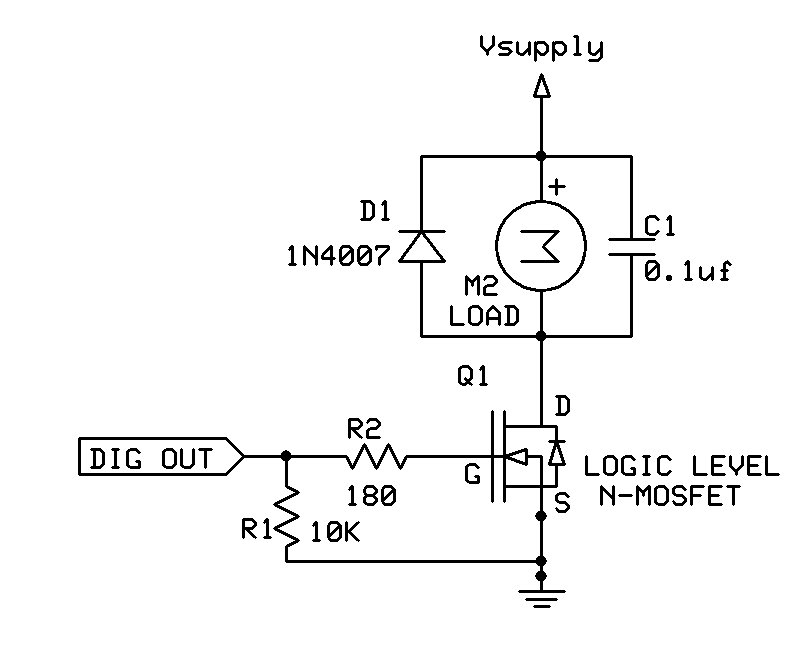
Other than that, I suppose spikes from the motor might be doing it. jremington's schematic, with the 100nF capacitor across the motor, will likely take care of that.

And, the 180Ω resistor in series with the Gate is a safety feather to mitigate in-rush current due to capacitance on the Gate.

Now, here's the thing about "Logic Level", there's a lot of "difference of opinion", and some of it is mired in rote learning, or from minds unwilling to bend into the creative realm of Amature Electronics.

Have a look at the following Graph:

This is from the IRF520 [Vishay] Datasheet. Notice that with 4.5V on the Gate, the maximum current possible [through the Drain-Source channel] is 1A. And at 5V [the next line up], that jumps to 2A. So, for currents at or below 2A, this MOSFET could be considered "Logic Level" -- as long as what you are driving doesn't need more than 1A [at a VDD of 4.5V] and 2A [at a VDD of 5.0V]. And in the hobbyist world, onee can make sure VDD is at 5V or even at 5.5V for a whopping 3.5A!

Now, there is a Caveat: Let's look at 5V: Notice how the lowest Drain-to-Source voltage is around 1.5V. So, if this MOSFET is driving something at 2A, that's a wattage of 2 * 1.5 = 3W, which is well within the margins on this device, but still, without a heatsink, it's gonna get hot. Also, that's a pretty high "On" voltage. I mean, if you're driving 12V, that's not too bad, but we can do better, if we tighten up the requirements, and shot for more like 1/2 Watt. That would be a max of around 1.1A [the point along the 5V line, where the VDS is 0.45V]. So, within our stricter requirements, this is even more justifiably "Logic Level".

See...most would say, "Dude, it's ridiculous to call this a Logic Level MOSFET, and even more ridiculous to run this thing at only 1A -- I mean, come on! It's designed for more like 6A!!"

And I would say, "If all you got is a lousy IRF520, because that's what came with the kit, then, hey, flaunt convention--if it gets the job done, then why not?!?"

I think the distinction to be made here is: "Fully Logic Level" vs "Partially Logic Level"

OR

Logic Level for Dummies vs Logic Level for Bad A$$ MacGyver Hobbyists!

ReverseEMF:
To address why your Pro Mini's are frying, I've found that the cheap knock-offs that are available on eBay, often can handle 12V--The regulator fries.

You mean "I've found that the cheap knock-offs that are available on eBay, often can not handle 12V -- The regulator fries."

ReverseEMF:
And, the 180Ω resistor in series with the Gate is a safety feather to mitigate in-rush current due to capacitance on the Gate.

Yeah, I had a mind to explain that. As long as it is placed after the pull-down, so that it does not - even if ever so slightly - form a voltage divider.

ReverseEMF:
Have a look at the following Graph:

The one I was using in my last explanation. Nice enlargement.

ReverseEMF:
Please DON'T Private Message to me, what should be part of the Public Conversation -- especially if it's to correct a mistake, or contradict a statement! Let it ALL hang out!!

OK, if you say so! I was going to just mention the first omission privately. :roll_eyes:

Paul__B:
OK, if you say so! I was going to just mention the first omission privately. :roll_eyes:

No, it's fine -- I flubbed, and a correction is needed. I will, now, go correct it :wink:

And, regarding the switch to 5V. I agree, that's just fine. Maybe the intent was to make sure it default to LOW, when the switch is open.

But, I think the point might be, that you can avoid the external resistor, if you tie the switch to ground, then use the Arduino's internal pull-up.

Also, because one has to do the whole Attach-Post-Modify in order to embed an image, some of you may not have seen my full post, a few back [#13].

Very interesting. So the button resistor bit is mostly a good practice, practicality thing?

Wow, thank you for such a detailed explanation, It makes sense! I also really enjoyed your humor analogies! I'll definitely aim to be a "Bad A$$ MacGyver Hobbyist!" XD

Thank you both so much for your reply's. I actually understand a bit more than I did!
Here is a link to a new post I just made to the forum, maybe you guys could help with that, too? Turns out, it was my wiring that was killing the boards.
Link

toxicxarrow:
Wow, thank you for such a detailed explanation, It makes sense! I also really enjoyed your humor analogies! I'll definitely aim to be a "Bad A$$ MacGyver Hobbyist!" XD

Your Welcome - glad someone appreciates my humor :wink:

toxicxarrow:
Here is a link to a new post I just made to the forum, maybe you guys could help with that, too? Turns out, it was my wiring that was killing the boards.

The link appears to be missing.

ReverseEMF:
The link appears to be missing.

REEEE! Fixed.
Link