So I have my Arduino Uno plugged into a wall socket and used the vin pin to power the magnet of the relay. I figured that if i could find out how much power is output through the vin I could program a pin to output that much power, after research I assumed that the vin puts out at max 12v, maybe 7v?, and I also keep reading about the numbered pins that the high is defaulted to 5v. can I exceed this voltage with numbered pins or is that not possible. and can i somehow use code to control the relay?
A digital pin cannot output more voltage than the Vcc of the processor, period. You can connect the pin to a transistor to switch higher voltage to control your relay. Use code to control the voltage to the relay by controlling the pin.
OT. Larry, is this graphic and your similar switch graphic in a sticky somewhere?
groundFungus:
OT. Larry, is this graphic and your similar switch graphic in a sticky somewhere?
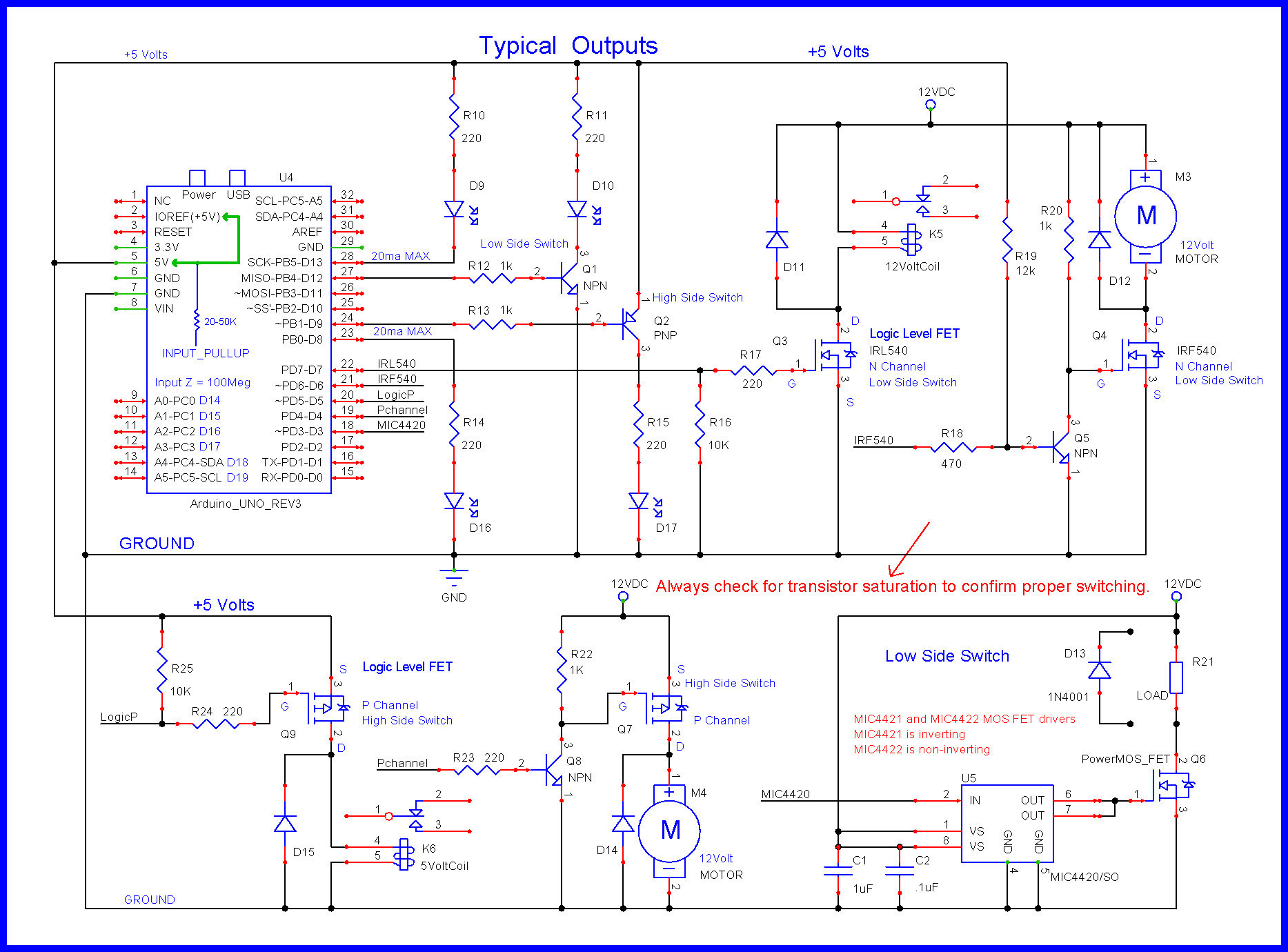
I posted them somewhere on the forum then copied the URLs to have at hand when needed.
Outputs
http://forum.arduino.cc/index.php?action=dlattach;topic=588494.0;attach=288418
Inputs
http://forum.arduino.cc/index.php?action=dlattach;topic=493392.0;attach=221459
To make it simple, the digital outputs will at most output approximately 4.8 to 4.9 volts.
Here's how the voltages breakdown:
-
Your wall adapter reduces the 120V (or 220 V in EU) to approximately 12 Volts.
-
This 12 volts goes into the uno circuit board.
-
A voltage regulator on the uno circuit board reduces the 12 V to 5V
-
This 5V is supplied to the processor (often this supply is called "Vcc")
The result is the processor cannot output any more that the input, here 5V.
Also know the processor is designed to work at no more than 5.5 Volts so attempting to put 6 or 7 volts on the processor in hopes of getting more voltage out will fail, because the processor will be damaged and stop working.
The other folks have kindly provided suggestions to use a transistor or Mosfet to allow the 5V processor to control higher voltages.
Isaac_Murray:
So I have my Arduino Uno plugged into a wall socket and used the vin pin to power the magnet of the relay. I figured that if i could find out how much power is output through the vin I could program a pin to output that much power, after research I assumed that the vin puts out at max 12v, maybe 7v?,...
In addition to the fine answers supplied by others on this forum, I would like to address your apparent confusion regarding the nature of "Vin". Vin is an Input. As such, Vin doesn't output anything. It's the supply, connected to Vin, that is doing the outputting. When you connect something to the Vin pin, what you are doing, essentially, is connecting to the supply. And, in such a case, it will be the supply, supplying [hence the name], the current, that will be causing power to be consumed. The current doesn't come out of the Vin pin. Current will flow out of the Supply, and divide at the point where the connection is made [at Vin]. Some of the current will flow into the Uno, and some will flow to whatever is connected to Vin [assuming there is, actually, a current path].
Also, it's not correct to say that Vin "puts out at max[sic] 12V". Vin doesn't put anything out. The 12V and 7V that you are referring to, are the Maximum, and Minimum voltages that will result in proper function of the Uno. Voltages higher than 12V will, possibly, damage the Arduino [and definitely, voltages greater than 16V!]. Also, the Uno needs a voltage [at Vin], greater than 7V, for it to function properly [sure, you might get away with less, but then you'll be out of spec, which means, if it goes wonky, don't blame the manufacturer ![]() ]
]
So, the proper way to say that is: "Only voltages between 7V and 12V should be applied to Vin".

Using a 5V pin can give you a higher output voltage by using the 5V as the input to a voltage doubler. Using that voltage to power something, from an Arduino, would not, most likely work with limited current sourcing capabilities and other, obvious, reasons. Still, the answer is yes, you can use digitalWrite() to make the Arduino pins output higher than 5V.
Isaac_Murray:
can I exceed this voltage with numbered pins or is that not possible. and can i somehow use code to control the relay?
No not with software. A relay should never be connected to an Arduino pin anyway, even if it is a 5V relay as while the Arduino can provide a 5V output it should only be called on to supply 40mA before you start damaging the pin.
To drive a relay of 12V you need to connect it to a transistor or FET ( see reply #2 ) and put a reverse biased diode across the relay coil to prevent very high voltages ( 100V or more ) being generated when the relay turns off.
Isaac_Murray:
So I have my Arduino Uno plugged into a wall socket and used the vin pin to power the magnet of the relay. I figured that if i could find out how much power is output through the vin I could program a pin to output that much power, after research I assumed that the vin puts out at max 12v, maybe 7v?, and I also keep reading about the numbered pins that the high is defaulted to 5v. can I exceed this voltage with numbered pins or is that not possible. and can i somehow use code to control the relay?
A logic device is just a bunch of switches. The pins get switched to either supply rail (ground for LOW,
Vcc for HIGH). The switches on an ATmega chip are about 40 ohms or so, as that's the resistance
of the MOSFETs used for each pin's output driving.
No amount of switches can create a voltage outside the applied supply voltage range (0..5V)
The chip is damaged instantly and permanently if a pin has an out-of-range voltage imposed on it
(more than about Vcc+0.5V, or less than GND-0.5V) The chip is not able to handle running
at more than 5.5V Vcc.
A microcontroller is outputting logic signals, its not switching lots of power, that's a job for a
driver chip.
So what are the details of this relay?
Idahowalker:
Still, the answer is yes, you can use digitalWrite() to make the Arduino pins output higher than 5V.
Still the answer is no, there is nothing you can do in software to make the Arduino’s pin output any higher than the Vcc of the chip. Which if you recall was the actual question.
However you can do things with extra hardware to do this, of which a voltage doubler circuit on the end is perhaps the silliest and least useful piece of hardware you could use. Also with that circuit you show no means of turning it on or off with a digital write.
BUUUUUUT...
It sounds like you already have the higher voltage [since you were talking about using Vin, and 12V, ans such]. If that's true, then there is a hardware solution -- something called a driver transistor [or voltage translator]. Below are two versions. For low power cases, a BiPolar will usually do the job. But in most cases the MOSFET solution is preferred -- and is excellent for both low power and high power cases [though, in any High Power situation, there are caveats that will, likely, need to be addressed in future conversations].
BiPolar Solution:

MOSFET Solution:

Resistor values, for the BiPolar case, depend on the amount of current the Transistor will be switching. Rule of thumb formula is as follows:
R[sub]1[/sub] = (V[sub]CC[/sub] - V[sub]BE[/sub])*10/I[sub]C[/sub]
In the case of the Arduino Uno, V[sub]CC[/sub] = [b]5V[/b]. V[sub]BE[/sub] is usually around [b]0.65V[/b] to [b]0.7V[/b] [consult the datasheet]. So:
R[sub]1[/sub] = (5 - 0.65)*10/I[sub]C[/sub]`` = 44/I[sub]C[/sub]
So, if the Transistor will be switching a maximum of, say, 300mA, then R[sub]1[/sub] will be:
44/300mA = 147Ω or standard 5% value
** **150Ω** **
[see Note 1, below]
** **10K** **
for [b]R[sub]3[/sub][/b] is pretty standard.
The MOSFET case is easier [at least at the "hobbyist" level]:
Just assume a max current of 20mA [due to input capacitance on the Gate of the MOSFET] and you get:
R[sub]2[/sub] = V[sub]CC[/sub]/20mA = 5/20mA = [b]250Ω[/b] or standard 5% value of either [b]240Ω[/b] or [b]270Ω[/b].
And, again, [b]10k[/b] for [b]R[sub]4[/sub][/b] ought to do it -- though this can go higher -- like [b]100k[/b] or so.
Note 1: Here's the formula for determining what the Base current will be, on a BiPolar transistor:
I[sub]B[/sub] = (V[sub]CC[/sub] - V[sub]BE[/sub])/R[sub]1[/sub] = 4.4/150 = [b]29mA[/b]!
The Maximum current an Arduino Uno output can "safely" deliver is spec'ed at [b]40mA[/b]. But, if you look at the DataSheet for an ATmega328P, the Arduino's MCU, [b]20mA[/b] is indicated as the "test current" for the various Output Pin specifications -- which suggests that the recommended operating max is [b]20mA[/b]. So, [b]29mA[/b] is in that ambiguous region between claimed max, and what is, probably, the best working max.
And, what this, bottom line, illustrates, is, for currents above, probably around [b]200mA[/b], it's better to use a MOSFET. And, I personally, always use a MOSFET, even for currents below [b]200mA[/b].
Note2: In the formulas, above, I left out such things as the pin output high voltage at load, 'cuz, I figured this was complicated enough for the OP.
then there is a hardware solution
No one ever disputed that there was a hardware soloution. The OP like many beginners us scared of hardware and wanted a pure software soloution, which does not exist.