im trying to run an op-amp circuit off a single 9v battery. but i cant get the +-V i need from that without some messing around with reference ground. basically i want to set a reference ground of 4.5V using a voltage divider from the 9v. then i will have plenty of +-V for my op-amp (the input wont be higher than 1v and the output will not exceed +-2v.) will this damage the arduino? ive tried using the arduino before (when i was just getting into MCs w/o grounding the 2 circuits together as one with horrid results.) i have used Virtual grounds before on other IC's without an issue... just dont know how my arduino would hold up...
i also dont want to go down the road of oscillating the signal and sending it threw a center tap transformer and then re-rectifying it.
any other ideas that might make this project possible?
The Arduino won't like the -2volt.
More info about the opamp circuit is needed to give the right advise.
I assume you want to connect the opamp output to an analogue input.
There are rail to rail opamps that can run on the Arduinos 5volt suply.
Leo..
im hoping when all is said and down the arduino will never see the negitive voltages via an inverted op-amp (sorry i didnt mention it). now that im thinking of it i think just a smaller offset of 3v would be better, so i can make a full 5v output from the final op-amp.
the idea behind this project im doing is to make a tempurature sensor from basic non-tempurature specific devices (so thermisters thermocouples ect are out) so as a group we all decided on using diodes with an op-amp. i dont want to get into specifics on the project but basically we can have either positive in and negitive out, or negitive in and positive out. i thought the 2nd would be harder.
if you want i can throw together a basic diagram on my multisim to show you whats happening.
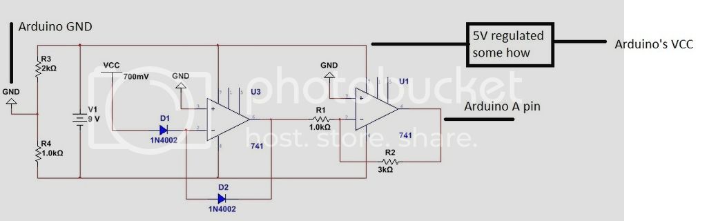
heres a basic idea of whats going on. please note i will most likely be using a better source for my 3V (that might even change) and none of those values for resistors are set at all with thought
some quick explanation might help. as D1 changes in temp, the current through D1 (which is the same as through D2) will change. this forces the op-amp 1 to change its output to allow that much current to flow through D2. so the output will be proportional to the temp. of D1. i hope that makes sense?
when it gets to the arduino i want analog pin be 1 degree for every 2 steps on analog. so it gives it a half a degree resolution.
You might be able to convert your temp sensor circuit to run off the Arduino's 5volt rail.
With e.g. a cheap low voltage LM324 opamp (~0-3.5v out). The ancient 741 won't work here.
Or make it easier on yourself and use e.g. the LM35 or LM36.
10mv/degree C = ~0.5C per digital step. Better if you use a lower Aref in your code.
Leo..
The lm35/6 would break the rule for non thermo device. And i need to have negitive somewhere in the ciruit... Maybe i can just use 4 aa batteries and power the arduino across those with a diode droping from vin. Ive read the arduino can do 5.5v so a single diode drop should safely drop that half volt if not more right?
Oh forgot to mention. Those 741s are there just cause i was too lazy to look at the specific op-amp we were supplied i think i have
I don't see the function of D2 in your schematic. Another temp depending part. This would basically do the job on a single 5volt rail.
Replace ZD1 with a cheap 3mm red LED (not the high brightness type).
That will give you a stable forward/zener voltage of ~1.8volt.
Negative supply pin of the opamp to GROUND. Positive supply to Arduino's 5volt.
Use a low voltage rail to rail out opamp. or try the LM324 with 2.56v Aref.
Leo..