You want to create a flowchart after writing the program ? That seems the wrong way round to me. How did you know how it would operate before writing the program ?
Have you tried searching the forum for other topics involving flowcharts ?
This flowchart is trivial.
The Setup() portion is simply each instruction, no decisions (if's) etc.
The loop has only one decision (green block in post #8.
left side of the decision is for temperature >50
(
digitalWrite(motor, HIGH);
digitalWrite(LedRed, HIGH);
digitalWrite(LedGreen, LOW);
lcd.print("ON ");
}
[quote="syzwnzhr, post:1, topic:883070"]
if (Temperature > 50){
digitalWrite(motor, HIGH);
digitalWrite(LedRed, HIGH);
digitalWrite(LedGreen, LOW);
lcd.print("ON ");
}
the right isde of the decision is code in the else braces ()
I think the key here is for you to read each line and understand what each line of code does. Then you can work on what the program does.
Flowcharts can be more or less detailed. In many cases it's sufficient to reflect the program structure with loops and decisions only. The remaining statement sequences can stay compact blocks with some verbose description.
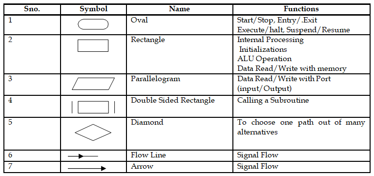
1. In Flow Chart Programming , the solution of a problem is described by the interconnections of a set of pre-defined ‘Geometrical Figures’ . The flow chart is a helpful tool for writing the assembly language or HLL codes. It is a good practice that we make a flow chart for every program we write and the professional people usually do it. A flow chart helps remembering the logic of the solution of the problem and assists in carrying out quick modification of the program in later times.
2. The symbols, names and functions of these figures are included in Fig-1. There is no ‘translation program’ for converting the ‘Flow Chart’ into machine codes/HLL codes.
5. Optimization of the sketch of Step-4 after removing of labels and goto statement. (Note that using of goto statement in programming is discouraged; however, it is a helpful tool for debugging a complicated non-functioning program and I used it a lot during the development phase of the Monitor Program for an 8086 based Trainer.)
6. Now carry out reverse engineering and try to draw Flow Chart for the codes of your sketch of Post-1. I can help you if you briefly describe the functioning of your sketch.