Can`t recognize CAN messages using nano + MCP2515

Hi guys.
I'm new in arduino, coding and all this things, so i hope my problem is simple, BUT I`ve looked over many topics here and haven't find 1 similar problem :(.
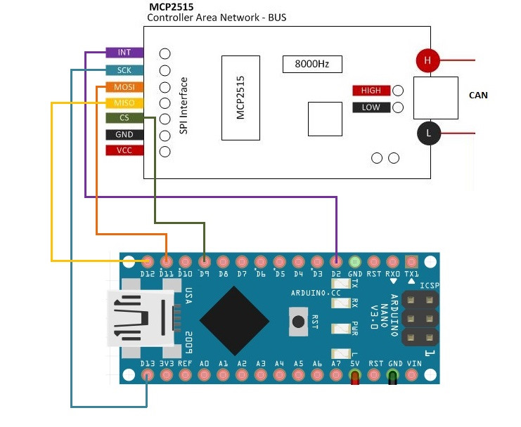
I have combination of CAN Shield "Niren" with MCP2515 and arduino nano. Here is the wiring diagram: link

Also i have a properly working CanHacker https://canhacker.com device with CarBUSAnalyzer installed on my PC, that helps me with testing.

Now I m trying to recieve messages from CAN and send some there, and there's no problem with sending, as you could see further, but i can recieve no messages with uncorrupted data (ID, DLC, data bytes) in it.
I've tried two libraries that works with MCP2515:

  1. Autowp arduino-mcp2515 lib
    Using this lib gives me no incoming ID from the message (id=1), but gives some DLC and data (but data is incorrect).
    Modified code from the example:
#include <SPI.h>
#include <mcp2515.h>

struct can_frame canMsg;
MCP2515 mcp2515(9);


void setup() {
  Serial.begin(9600);
  
  mcp2515.reset();
  mcp2515.setBitrate(CAN_500KBPS, MCP_8MHZ);
  mcp2515.setNormalMode();
  
  pinMode(2, INPUT);

  Serial.println("------- CAN Read ----------");

  struct can_frame frame;//initial test frame
  frame.can_id = 0x17330500 | CAN_EFF_FLAG;
  frame.can_dlc = 3;
  frame.data[0] = 0x20;
  frame.data[1] = 0x5F;
  frame.data[2] = 0x02;
  
  Serial.println("Sending test message: 0x17330500, 3, 20 5F 02");
  mcp2515.sendMessage(MCP2515::TXB1, &frame);
}

void loop() {
  if (mcp2515.readMessage(&canMsg) == MCP2515::ERROR_OK) {
    Serial.print("Arduino recieved the message with: Id ");
    Serial.print(canMsg.can_id, HEX); // print ID
    Serial.print(", DLC "); 
    Serial.print(canMsg.can_dlc, HEX); // print DLC
    Serial.print(", data ");
    
    for (int i = 0; i<canMsg.can_dlc; i++)  {  // print the data
      Serial.print(canMsg.data[i],HEX);
      Serial.print(" ");
    }

    Serial.println();      
  }
}

Log from the serial after sending one message from the canhacker:

------- CAN Read ----------
Sending test message: 0x17330500, 3, 20 5F 02
Arduino recieved the message with: Id 1, DLC 3, data 0 4F FF

and that`s what I see in CarBUSAnalyzer:
photo_2023-03-25_19-15-07
Out message (that one which Arduino recieves) is in the bottom, In message is on the top of the screen.

  1. Cory J. Fowler`s MCP_CAN_lib

This lib gives me some incorrect ID, but 0 DLC and no data at all...

Code:

// CAN Receive Example
//

#include <mcp_can.h>
#include <SPI.h>

long unsigned int rxId;
unsigned char len = 0;
unsigned char rxBuf[8];
char msgString[128];  // Array to store serial string

#define CAN0_INT 2  // Set INT to pin 2
MCP_CAN CAN0(9);    // Set CS to pin 9


void setup() {
  Serial.begin(9600);

  // Initialize MCP2515 running at 16MHz with a baudrate of 500kb/s and the masks and filters disabled.
  if (CAN0.begin(MCP_ANY, CAN_500KBPS, MCP_8MHZ) == CAN_OK)
    Serial.println("MCP2515 Initialized Successfully!");
  else
    Serial.println("Error Initializing MCP2515...");

  CAN0.setMode(MCP_NORMAL);  // Set operation mode to normal so the MCP2515 sends acks to received data.

  pinMode(CAN0_INT, INPUT);  // Configuring pin for /INT input

  Serial.println("MCP2515 Library Receive Example...");
  Serial.println();
}


unsigned long exampleId = 0x17330110 | 0x80000000UL;
byte exampleData[8] = {0x00, 0x01, 0x02, 0x03, 0x04, 0x05, 0x06, 0x07};


void loop() {
  if (!digitalRead(CAN0_INT))  // If CAN0_INT pin is low, read receive buffer
  {
    CAN0.readMsgBuf(&rxId, &len, rxBuf);  // Read data: len = data length, buf = data byte(s)

    if ((rxId & 0x80000000) == 0x80000000)  // Determine if ID is standard (11 bits) or extended (29 bits)
      sprintf(msgString, "Arduino recieved the message with: Extended ID 0x%.8lX  DLC %1d", (rxId & 0x1FFFFFFF), len);
    else
      sprintf(msgString, "Standard ID: 0x%.3lX       ,DLC: %1d  Data:", rxId, len);

    Serial.println(msgString);


    Serial.print("Arduino sending a message with: ID = 0x17330100, Extended CAN Frame, Data length = 8 bytes, 'data' = 00 01 02 03 04 05 06 07");
    byte sndStat = CAN0.sendMsgBuf(0x17330100, 1, 8, exampleData);
    if (sndStat == CAN_OK) {
      Serial.println("Message Sent Successfully!");
    }

    Serial.println();
  }
}

/*********************************************************************************************************
  END FILE
*********************************************************************************************************/

Serial log after sending 3 messages from CanHacker:

Arduino recieved the message with: Extended ID 0x00130010  DLC 0
Arduino sending a message with: ID = 0x17330100, Extended CAN Frame, Data length = 8 bytes, 'data' = 00 01 02 03 04 05 06 07
Message Sent Successfully!

Arduino recieved the message with: Extended ID 0x1FF30010  DLC 0
Arduino sending a message with: ID = 0x17330100, Extended CAN Frame, Data length = 8 bytes, 'data' = 00 01 02 03 04 05 06 07
Message Sent Successfully!

Arduino recieved the message with: Extended ID 0x1FF30010  DLC 0
Arduino sending a message with: ID = 0x17330100, Extended CAN Frame, Data length = 8 bytes, 'data' = 00 01 02 03 04 05 06 07

and that`s what I see in CarBUSAnalyzer:
photo_2023-03-25_19-19-51
note that I sent three identical messages, but the id of the first message received by the arduino is different from the others.

Please help me guys, what am i doing wrong? I`ve doublechecked my devices, there are no problems and no errors with soldering.

Does CarBUSAnalyzer have a loopback mode where you can check the transmitted data sent from from the CanHacker ?

There's also a loopback demo sketch in the Cory Fowler library that tests the Arduino MCP2515 send and receive circuitry.

1 Like

i think yes, will try later. thx
but i believe it works as it should, because:

  1. i`ve tried to send same messages to the car CAN and it understood them
  2. arduino have same problems when i connect it to the car: wrong Ids etc.

Try running the loopback demo in the Cory Fowler library.

How are you powering the MCP2515? There are no power wires shown on your wiring diagram.

1 Like
  1. Powering of the MCP2515: I have connected GND and VCC from it to the GND and 5V ports on the arduino.
    Arduino is powering from the usb port at the moment.

  2. Running the loopback demo from Cory Fowler library:
    only 16>8 MHZ and serial baudrate was edited.

/* CAN Loopback Example
 * This example sends a message once a second and receives that message
 *   no CAN bus is required.  This example will test the functionality 
 *   of the protocol controller, and connections to it.
 *   
 *   Written By: Cory J. Fowler - October 5th 2016
 */

#include <mcp_can.h>
#include <SPI.h>

// CAN TX Variables
unsigned long prevTX = 0;                                        // Variable to store last execution time
const unsigned int invlTX = 1000;                                // One second interval constant
byte data[] = {0xAA, 0x55, 0x01, 0x10, 0xFF, 0x12, 0x34, 0x56};  // Generic CAN data to send

// CAN RX Variables
long unsigned int rxId;
unsigned char len;
unsigned char rxBuf[8];

// Serial Output String Buffer
char msgString[128];

// CAN0 INT and CS
#define CAN0_INT 2                              // Set INT to pin 2
MCP_CAN CAN0(9);                               // Set CS to pin 10


void setup()
{
  Serial.begin(9600);  // CAN is running at 500,000BPS; 115,200BPS is SLOW, not FAST, thus 9600 is crippling.
  
  // Initialize MCP2515 running at 16MHz with a baudrate of 500kb/s and the masks and filters disabled.
  if(CAN0.begin(MCP_ANY, CAN_500KBPS, MCP_8MHZ) == CAN_OK)
    Serial.println("MCP2515 Initialized Successfully!");
  else
    Serial.println("Error Initializing MCP2515...");
  
  // Since we do not set NORMAL mode, we are in loopback mode by default.
  //CAN0.setMode(MCP_NORMAL);

  pinMode(CAN0_INT, INPUT);                           // Configuring pin for /INT input
  
  Serial.println("MCP2515 Library Loopback Example...");
}

void loop()
{
  if(!digitalRead(CAN0_INT))                          // If CAN0_INT pin is low, read receive buffer
  {
    CAN0.readMsgBuf(&rxId, &len, rxBuf);              // Read data: len = data length, buf = data byte(s)
    
    if((rxId & 0x80000000) == 0x80000000)             // Determine if ID is standard (11 bits) or extended (29 bits)
      sprintf(msgString, "Extended ID: 0x%.8lX  DLC: %1d  Data:", (rxId & 0x1FFFFFFF), len);
    else
      sprintf(msgString, "Standard ID: 0x%.3lX       DLC: %1d  Data:", rxId, len);
  
    Serial.print(msgString);
  
    if((rxId & 0x40000000) == 0x40000000){            // Determine if message is a remote request frame.
      sprintf(msgString, " REMOTE REQUEST FRAME");
      Serial.print(msgString);
    } else {
      for(byte i = 0; i<len; i++){
        sprintf(msgString, " 0x%.2X", rxBuf[i]);
        Serial.print(msgString);
      }
    }
        
    Serial.println();
  }
  
  if(millis() - prevTX >= invlTX){                    // Send this at a one second interval. 
    prevTX = millis();
    byte sndStat = CAN0.sendMsgBuf(0x100, 8, data);
    
    if(sndStat == CAN_OK)
      Serial.println("Message Sent Successfully!");
    else
      Serial.println("Error Sending Message...");

  }
}

/*********************************************************************************************************
  END FILE
*********************************************************************************************************/

That is what I have in the monitor:

Entering Configuration Mode Successful!
Setting Baudrate Successful!
MCP2515 Initialized Successfully!
MCP2515 Library Loopback Example...
Message Sent Successfully!
Standard ID: 0x000       DLC: 0  Data:
Message Sent Successfully!
Standard ID: 0x000       DLC: 0  Data:
Message Sent Successfully!
  1. CarBUSAnalyzer does't have loopback mode, but my device has two CAN channels so I can connect one to another and take a look what's goin on there
    image
    As you can see, I have sent message with 17330500 from CAN1 and it has appeared in the "recieve" channel of CAN2; same on the other way: message with 17330100 was sent.

The sent and received messages in the MCP2515 loopback test don't match, therefore the board is faulty.

1 Like

ok, maybe problem can be in arduino? other problem caused by chinese chip is here: Arduino nano runs 4 times slower
I think it's better to try another nano first

Are you using a LGT8F328P?

Try a genuine ATmega328.

1 Like

Thanks for your support, @mikb55

The case I had described was caused by that chip and I was extremely close to buying new nano, but unexpectedly found another way.

The problem was I flashed my arduino clone like standart arduino nano, but as a beginner I didn't even know there are different devices and different ways to flash them.
Finally i found materials about exactly my chip: GitHub - dbuezas/lgt8fx: Board Package for Logic Green LGT8F328P LGT8F328D and LGT8F88D
and the manual about flashing exactly my device: Nano 328P-LGFP32 V3.1 · Issue #210 · dbuezas/lgt8fx · GitHub

Arduino IDE settings for Arduino Alpha Nano V3.1 LGT8F328P LQFP32

image

now I have no issues neither with CANBUS nor with clock.

This topic was automatically closed 180 days after the last reply. New replies are no longer allowed.