So I want to build a relatively simple circuit, with an LED and a power source to provide more current to the LED than the arduino uno R4 can provide, so i am using a transistor (BJT, npn 2N2222 A) I am aware that i can select a resistor value for the base in order to increase the collector current to a specific value. My question is, is there a way that i can have the collector current be based on the voltage of the supply (Vcc) while still being amplified (BJT in active region, for certain range of Vcc values).
So as shown in the diagram i would like, when i increase Vcc i want the collector current to also increase and the transistor be in the active region for a range of Vcc values (up untill the point that either the Vcc source reaches its max current(Ic) or the I/O pins reach their max current(Ib)) . Does a relatively simple transistor connection exist that accomplishes this?
You need to add a resistor in series with the LED D1. Otherwise you will burn the LED ( and maybe the transistor ). The current through the LED then varies with Vcc. The base current should be high enough, that the 2N2222 is always completely switched ON.
i can have the collector current be based on the voltage of the supply
Of course it varies, but the resulting current is not predictable for a given transistor.
Transistor parameters in the data sheet are nominal, and can vary greatly from one transistor to another. Professional designers plan for sample variations of a factor of 2 or more.
What you describe is a voltage controlled current source, which is trivial to make using an op amp. A web search will find example circuits.
It is not hard, here is the schematic: D1 and D2 are forward biased to supply to supply the base of the transistor. I use this circuit but I generally use a LED in place of the two diodes. R1 and the bias determine the current.
i regulate the brightness from the arduino, i basically want to regulate the max brightness from the Vcc source , so i already do use PWM to control the base current and thus the collector current, it's just that i want that, when i increase the voltage source the cap on the collector current also increases. But thanks for the diagram, it might be useful in the future
The circuit in post#7 works, but I prefer a two-transistor one like this diagram.
Calculate Rsense for 0.65volt@the required current. R control can simply be 330 Ohm. Drive can be 2N2222/BC337. Feedback can be 2N3904/BC547
Leo..
By the way, a resistor can be viewed as a voltage controlled current source, and when in series with an LED, the circuit has the fascinating property that the LED current increases with the supply voltage!
Let me explain it for the OP.
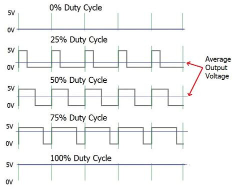
PWM stands for Pulse Width Modulation. It's a technique used to simulate an analog signal using digital means. It works by switching a digital signal (on/off) on and off at a very high frequency and varying the proportion of time the signal is on versus off — this proportion is called the duty cycle.
Key Concepts:
Duty Cycle: The percentage of time the signal is "on" during one cycle.
    100% duty cycle: always on
    50% duty cycle: on half the time, off half the time
    0% duty cycle: always off

Frequency: How many cycles occur per second (measured in Hz).
Where PWM is Used:
Motor speed control (e.g., in robotics or drones)
LED brightness control
Audio signal generation
Power delivery in DC-DC converters
Communication protocols in microcontrollers
Example:
To dim an LED using PWM:
If the LED is switched on 50% of the time (50% duty cycle), it appears half as bright.
If it’s on 90% of the time, it appears almost fully bright.
Ok i didnt phrase it very well, but when the voltage source that supplys the base current (the arduino) takes the voltage High for x% of a cycle and takes the voltage Low for (100-x)% of a cycle (this proccess i assumed to be PWM), the brightness of my led increases and dims as expected. So in my case using what i above described as PWM did indeed work, and changed the brightness as expected,i may be wrong on my explanation but with the "PWM" i didnt really have an issue.
Yes but with the method that some people above said of using a resistor, so basically i wanted to be able to set a different max value for the range of the brightness of my led, and then use PWM to pick any value within that range, the first part was the issue, which has now been resolved thanks everyone
Thank you it worked, I was thinking about it a bit wrong, i thought that with a resistor at the base and using kirchoffs law that the base current would be constant and aproximating constant gain (which i guess is wrong) the collector current would also be constant and only the voltage at the collector would change. But in practice your solution is correct, so thanks. Also shoutout to another person above who also gave this solution