Can't connect to ATmega128 using Atmel clone development card and CP2102N serial bridge

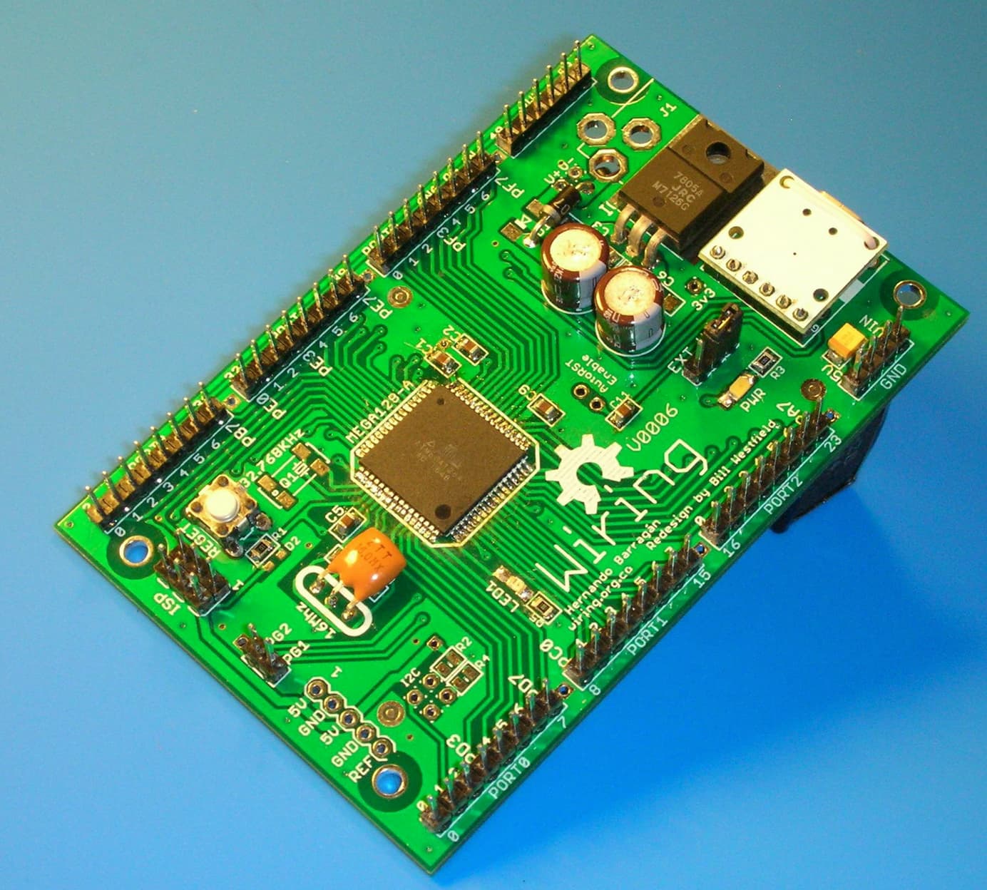
I bought a low cost ATmega128 development card and connected a CP2102 bridge to the card's ISP port with the following connections:

CP2102N ------------>>>>ATmega128 Processor Pin
TXD (out)-------------->>>>ATmega pin 2 RXD0/PDI (input)
RXD (in)----------------->>>>ATmega pin 3 TXD0/PDO(out)
DTR (out)--------------->>>>ATmega pin20(not RESET)(in) through 100nF capacitor

In addition, +5V from the USB port is connected to ATmega128 Vcc along with ground.

I found the MegaCore board package from MCUdude. I used File > Preferences > Additional Board Manager URLs to point to:

https://mcudude.github.io/MegaCore/package_MCUdude_MegaCore_index.json

to get the MegaCore Board Manager installed in the Arduino IDE. That was successful I believe. I was then able to select the MegaCore board and the ATmega128 option.

Additionally, I installed the CP2102 driver from Silicon Labs and when connected to my PC USB port showed as COM3 and as a functioning device.

In the Arduino IDE, I made a simple blink program that compiled fine but even though the IDE recognized a board on COM3, it could not upload and the sketch and failed with the following errors shown below.


avrdude: Version 7.2-arduino.1

  •     Copyright the AVRDUDE authors;*
    
  •     see https://github.com/avrdudes/avrdude/blob/main/AUTHORS*
    
  •     System wide configuration file is C:\Users\craig\AppData\Local\Arduino15\packages\MegaCore\hardware\avr\3.0.1\avrdude.conf*
    
  •     Using Port                    : COM3*
    
  •     Using Programmer              : urclock*
    
  •     Overriding Baud Rate          : 57600*
    

avrdude ser_open() error: cannot open port \.\COM3: The system cannot find the file specified.

avrdude main() error: unable to open programmer urclock on port COM3

avrdude done. Thank you.

Failed uploading: uploading error: exit status 1

Several things confuse me - The IDE shows me that COM3 is connected and the device manager in windows shows me the CP2102 device is working yet the IDE says it can't open COM3 and it can't open the urclock programmer on COM3 either. What file can it not find that the system specified?? Do I need to download something else?? Do I need to edit the avrdude.conf file??

I must be missing something fundamental??? I am assuming that I am connected to the PDI/PDO port of the ATmega and that this is a valid port for programming. Is this correct? Do I need to burn a bootloader first? If so, o I use the same port connections and the Arduino Burn Bootloader tool?

Any guidance would be greatly appreciated!!

Newtoatmega, welcome to the forum!

There appear to be several versions of Mega 128 dev boards including some with serial UART on board. Which one do you have please? Obviously you have a variant that requires an external USB-to-serial adapter.

Pin 20 on the Mega chip (although not necessarily on the board) is RESET and should not be left floating. It needs to be held in a High state for the MCU to run and is pulled low to effect a reset or hold the MCU in suspense. A 4.7k resistor between VCC and the RESET pad on the board should suffice and still allow the pin to be pulled low if required. Its not that critical and anything up to 10k could be used.

^AVR® Microcontroller Hardware Design Considerations

At present we have no idea whether your dev board provides for this or not?

I am using a no-name board from ebay. See this link:

Pin 20 of the ATmega128 is pulled up by 10 and a reset push button is provided. Inititially, I left pin 20 as is but then because I could not upload my sketch from the IDE, I capacitively coupled the DTR output of the CP2102N to the processor RESET pin believing that maybe it needed to be pulled low momentarily when the USB bridge was first communicated to.

Thanks for your help!

Ok, we have an onboard reset button so I guess that is taken care of. On boards such as the Uno and Nano, the DTR signal is indeed wired to RESET so as to force a reboot and loading of the bootloader whenever the serial port is opened.

It might be worth checking that, unless you are using an external one, that jumper J1 set for the onboard crystal. If the jumper is in the position shown in the photo in the link you provided, then its set for the socket where you plug in an external crystal.

Speaking of bootloaders, I am not sure whether these boards come with one pre-installed or not. Without a bootloader, nothing is going to happen when you connect to the serial port. It would first need to be uploaded via the ISP port using a USBASP programmer or another Arduino. If you have a USBASP (they are quite cheap to buy) then you don't need to use the serial port to program the chip anyway.

Hi @BitSeeker:

I did set the jumper for the on-card crystal (8 MHz). I think you identified the issue and it was one of my questions on my initial post - Does the borad include the bootloader? If the board does not come with a bootloader as you suggest and you are telling me that one must be programmed before the serial port can be used, I am guessing that is my issue!!

If I buy the USBASP programmer, my understanding is that I still need my USB-serial bridge to give me access to the serial monitor function in the IDE even if I can use the USBASP to program the Arduino sketches. Am I correct?

Thank you @BitSeeker

Since the Serial Monitor establishes a session with the serial port, if you need to monitor output from serial, then some means of physical connection, such as the CP2102 USB-to-serial bridge you mention, would still be required, yes.

There is no straightforward way to check whether the chip has a bootloader uploaded to it. If you can upload a sketch, then it must have one. Dumping and examining the content of the flash memory would be another way. The bootloader gets invoked after a reset. It then checks whether there is something to be uploaded. If so, then it handles the upload of the transmitted data into program memory. If, on the other hand there is not, then after a timeout period it proceeds to run the program that is already loaded into program memory. Without the bootloader, none of that can happen.

Just a note regarding the 128 for when you get around to burining the bootloader to it. I believe this board might be one of those where the MISO/MOSI pins on the programmer connect to the PE0 and PE1 pins on the 128 rather than MISO and MOSI as is the case with some other Arduino boards such as the UNO and Mega2560.

I mentioned in my previous post apart frm the USBASP, that it is possible to use another Arduino to program the 128. If you have one lying around, then here are the details of how its done:

https://docs.arduino.cc/built-in-examples/arduino-isp/ArduinoISP/

Why can't "they" clone a more useful board, like this one:

Hi @BitSeeker:

Thank you for the good advice. I did check my board and the ISP port uses PDI/PDO (pins 2 and 3 of the ATmega128 chip). My USBASP should arrive soon. My understanding is that I will be able to use the burn bootloader tool from the Arduino IDE. Is this correct?

Thanks

Hello @BitSeeker or others:

I received my USBasp programmer and using the MegaCore libraries installed using the "Additional Board Manger URLs" field and the correct GiTHub address, I was able to successfully run the Burn Bootloader option. It appeared successful to the best of my understanding of the console messages. I had to solve some USB port driver issues but ultimately, I was able to burn the bootloader and run a simple blink-like sketch and use the IDE option "Upload Using Programmer"

But I wanted to use the connection to the ISP port on my clone ATmega128 card with a serial bridge. My thought was that if the bootloader was properly working and my USB Bridge was too, then I could use "Upload" to transfer programs and to use the IDE's serial monitor.

I proved my USB CP2102 bridge was functioning by using PuTTY to simple no flow control TX-RX loopback and could see the transmitted characters at a number of BAUD rates from 9600 to 115,200. So I ma confident my CP2102 bridge and Silicon Labs driver are ok.

But when I am in the IDE, although the IDE shows my board is connected to the correct COM port (COM3 in my case), when I select "Upload", I get the following response:
##########################################################
avrdude: Version 7.2-arduino.1
*** Copyright the AVRDUDE authors;***
*** see avrdude/AUTHORS at main · avrdudes/avrdude · GitHub***

*** System wide configuration file is C:\Users\craig\AppData\Local\Arduino15\packages\MegaCore\hardware\avr\3.0.1\avrdude.conf***

*** Using Port : COM3***
*** Using Programmer : urclock***
*** Overriding Baud Rate : 4800***
avrdude urclock_getsync() warning: attempt 1 of 10: not in sync
avrdude urclock_getsync() warning: attempt 2 of 10: not in sync
avrdude urclock_getsync() warning: attempt 3 of 10: not in sync
avrdude urclock_getsync() warning: attempt 4 of 10: not in sync
avrdude urclock_getsync() warning: attempt 5 of 10: not in sync
avrdude urclock_getsync() warning: attempt 6 of 10: not in sync
avrdude urclock_getsync() warning: attempt 7 of 10: not in sync
avrdude urclock_getsync() warning: attempt 8 of 10: not in sync
avrdude urclock_getsync() warning: attempt 9 of 10: not in sync
avrdude urclock_getsync() warning: attempt 10 of 10: not in sync
avrdude urclock_recv() warning: programmer is not responding; try -xstrict and/or vary -xdelay=100
avrdude main() error: unable to open programmer urclock on port COM3

**avrdude done. Thank you.
##########################################################

What is this output telling me? I can look with a scope on the bridge TX line and see that some characters are being sent but nothing is returned to the bridge's RX line.

Just to clarify from my earlier post:

The TX output of my bridge is connected to ATmega128 pin 2 which is PE0 or PDI
The RX input to my bridge is connected to the ATmega128 pin 3 which is PE0 or PDO.

This is the same ISP port that I am able to use successfully with my USBasp programmer using "Upload with Programmer"

Am I fundamentally not understanding what the difference between "Upload" and Upload with Programmer"? Can I assume that the bootloader that I was able to burn in previousl into 388 bytes of FLASH was correct and taken from the Megacore board support package for the ATmega128 device?

Thank you in advance for helping me to understand the fundamentals of using the Arduino IDE and any guidance that would allow me to use the serial port bridge and not the USBasp device for uploading and access to the serial monitor.

When Sketch->Upload is used, this uploads the compiled program code via the serial port and requires the CP2102 UART bridge. If you want to be able to program using this method, then the bootloader is also required and needs tp be present.

On the other hand, Sketch->Upload Using Programmer will upload the compiled code using the programmer that has been configured in Tools-Programmer. In this case you are using the USBASP and the bootloader is not required.

This seems to indicate a timing problem. What does it do if you try to upload at 4800 baud?

After selecting the ATMega128 board under Tools, a number of additional sub-menu items will have appeared, one of which is Clock. If you are still using the internal 8MHz crystal, then make sure that 'Internal 8MHz' is selected.

You should also see a Bootloader item and if you are using Tx0/Rx0 the 'Yes(UART0)' option should be ticked. Possibly you might want to consider using UART1 instead? That way you can have both the USBASP programmer connected to the SPI port and the CP2102 UART bridge connected to RXD1 and TXD1 (PD2/PD3 or pins 27 & 28) at the same time. If I understand the setting correctly, you should be able to use this alternate serial port to program as well using Sketch->Upload. I am not sure how the serial port name is affected in this instance. It might be 'seen' as the default port i.e. 'Serial', or you might have to use 'Serial1'.

Provided that the correct board was selected when the bootloader was burned, then the correct bootloader code will have been uploaded to the board. However, after checking and, if necessary, adjusting the above settings, you will want to burn the bootloader again using the USBASP using the 'Upload Using Programmer' option to be sure that the new settings have been applied.

In any case, the clock setting does need to match the crystal frequency, otherwise Serial timing is affected and when the program runs, this will affect how the output is displayed in Serial Monitor. For example, if code is compiled for 16MHz and the board is actually running at 8MHz, then 9600 baud ends up becoming 4800 baud.... You could, of course, just set the Serial Monitor to 4800 baud, but ideally we want the port to run at the correct speed.

What you propose should therefore be possible to achieve. You should be able to program with the USBASP programmer using the 'Upload Using Programmer' option and view the output from your sketch in the Serial Monitor via the CP2102 UART bridge.

Hi @BitSeeker:

I did burn the bootloader using the USBasp device and made sure that I was using the EXT 8 MHz option for the clock since my board has the 8 MHz crystal. I also used the Tools menu to specify UART0 which I believe uses pins 2 and 3 of The ATmega128.

I did not seem to have any problem using the USBasp device to burn the bootloader and I had no problem using the Upload with Programmer to upload my small sketch and blink my test LED. I also confirmed the clock was oscillating at 8MHz on the scope.

The problem only occurs when I remove the USBasp device and place the CP2102 serial bridge on that port. The TX output of my bridge drives the RX or PDI pin 2 on the ATmega128 and the RX input of my bridge is driven by the TX or PDO pin 3 on the ATmega128. I have verified that the differentiated DTR signal (connected through a 100nF capacitor) is producing a few reset pulses when I first press the Upload button. There is a delay of about 120ms after the RESET goes high before I see the IDE send a character to the ATmega128. No matter which BAUD rate I choose, I get the same sync problem.

I took a second CP2102 bridge and connected the TX line that feeds RX0/PDI and connected it to the RX inpiut of my second bridge. Using PuTTY, I can see that the first character sent to the ATmega128 is the "0" character. After that, since the ATmega128 never replies back, a series of "spaces" are sent by the IDE until attempt 10 fails. I tried this experiment at multiple BAUD rates as well and get the same error.

So it seems like the protocol used by the IDE, which is set by the Mega core conf or board files may be an issue? How do I know that the proper bootloader was burned in the ATmega128 and is compatible with the IDE Upload protocol?

Did you use "upload using programmer" AFTER your did the "burn bootloader"? If so, that will have erased the bootloader.

Megacore recently switched from Optiboot to "urboot", which may or may not have interesting problems - I don't know how much experience there is with some of the less popular chips. (and no provision for bing backward compatible. Though I think urboot itself is supposed to be backward compatible...)
But your "upload" dialog looks weird:

*** Overriding Baud Rate : 4800***

I'm pretty sure the baud rate should be at least 57600 for an 8MHz chip (as it was in one of your earlier examples.

Could you make sure "verbose" is selected for both compile and upload, and post the full output when you attempt to upload the sketch (inside of code tags!)? I particularly want to see the avrdude command being used.

(and the full output from the "burn bootloader" command as well.)

1 Like

FWIW, I did put a urboot bootloader on my m128 board and was able to upload sketches. But it's a 16MHz board with a CH340 USB/UART...

Hi @westfw:
Indeed, I did use "Upload using Programmer" after asserting "Burn Bootloader". I did not understand that the "Upload Using Programmer" would overwrite the boot as I thought they were in different sections of FLASH.

I do have both verbose options set so I will repeat the Burn and Upload without using "Upload with Programmer" and see if I get a better result. I will send the detailed reseponses. By the way, I did prove to myself that I could exercise the avrdude.conf command with all of its switches from the DOS CMD window and get the same results. I even verified that if I added the -xdelay=100 command switch, I coukd see the delay from RESET going high to the first TX output character increase by 100ms. Unfortunately, increasing that delay did nothing. Now it is clear, I may never have had a valid boot section!!!
Thanks for your help!

They ARE different sections of flash (more or less), but ISP programming does not have the ability to erase them separately. The bootloader can erase flash one page at a time (~256 bytes), but the only command available during ISP programming is "erase entire chip."

Thank you @westfw!!!!

I burned the bootloader with my USBasp device, removed it and connected my CP2102 USB-serial bridge and then exercised an Upload of my blink test program and it worked correctly.

All of this time, I was running an Upload with Programmer immediately after burning the bootloader because I was an idiot and did not realize I was wiping out the bootloader.

I think I now have a working ATmega28 card.

This topic was automatically closed 180 days after the last reply. New replies are no longer allowed.