I'm a newbie and I'm trying to learn how to use an ESP controlled display.
I had tried with an ESP32 but as I kept crashing, I went back to testing with an ESP8266.
Here's my code with all the connections included:
#include <U8g2lib.h>
#include <SPI.h>
// Pin definitions
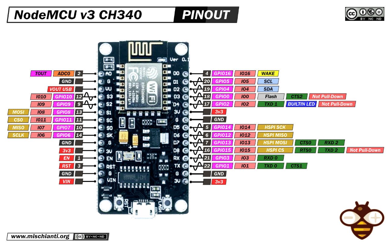
#define SCLK_PIN D5 // GPIO14 - DISPLAY PIN4
#define SDIN_PIN D7 // GPIO13 - DISPLAY PIN5
#define CS_PIN D3 // GPIO0 - DISPLAY PIN16
#define DC_PIN D2 // GPIO4 - DISPLAY PIN14
#define RESET_PIN D1 // GPIO5 - DISPLAY PIN15
// Initialize the U8g2 object for the SSD1322 display in software SPI mode
U8G2_SSD1322_NHD_256X64_F_4W_SW_SPI u8g2(U8G2_R0, SCLK_PIN, SDIN_PIN, CS_PIN, DC_PIN, RESET_PIN);
void setup() {
Serial.begin(115200);
Serial.println("Initializing the OLED display...");
// Check for the presence of the display by sending a command and verifying the response
if (u8g2.begin()) {
Serial.println("OLED display detected and initialized.");
u8g2.clearBuffer();
u8g2.setFont(u8g2_font_ncenB08_tr); // Select the font
u8g2.drawStr(0, 24, "Hello, World!");
u8g2.sendBuffer();
Serial.println("Message displayed on the screen.");
} else {
Serial.println("Failed to detect the OLED display. Check the connections.");
}
}
void loop() {
// Empty loop
}
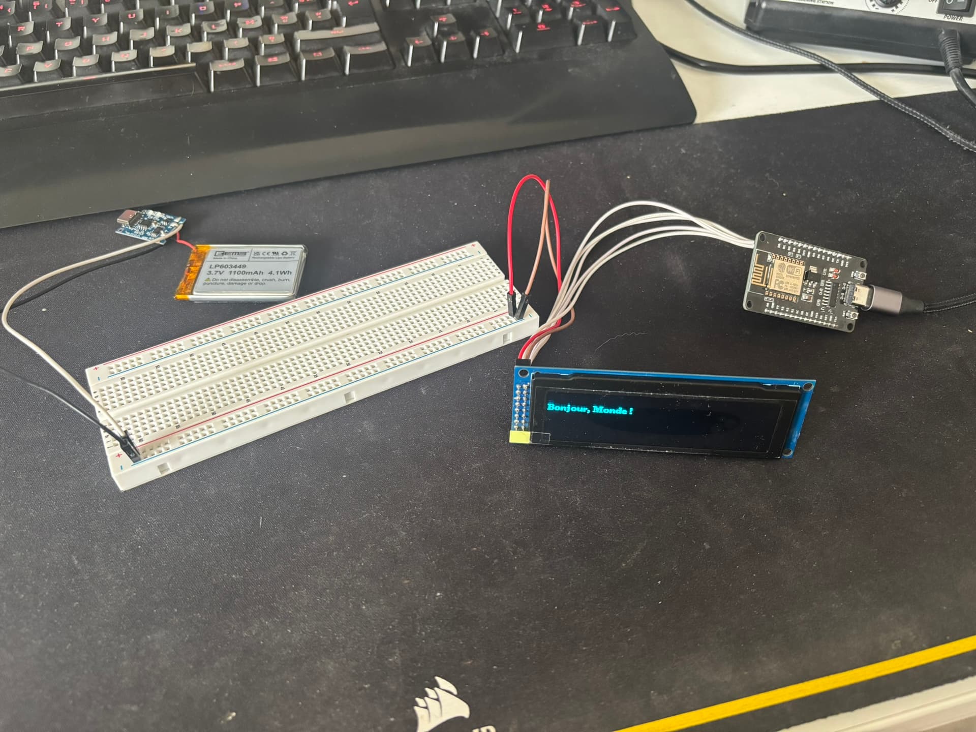
However, the display doesn't light up even though it's powered by a 3.7V battery. I can't figure out where my problem lies.
At first I thought it was the screen, I tried to change it with a new one but the problem continues.
However, the code executes well, as I receive my messages on the serial monitor.
Oh yes, you're right... Thank you
I can't move the resistors, I'm not equipped for that. I don't have a microscope and my soldering iron isn't going to help me much on sight. I can try, but I risk screwing it up.
So if I understand correctly, to make it work, not only do I have to adapt my code but I also have to adapt my connection to use the 8 data pins as well as the 3 control pins... But since my ESP8266 is limited... So in fact I'm more likely to recommend a new screen that allows 4-wire SPI.
Do we agree?
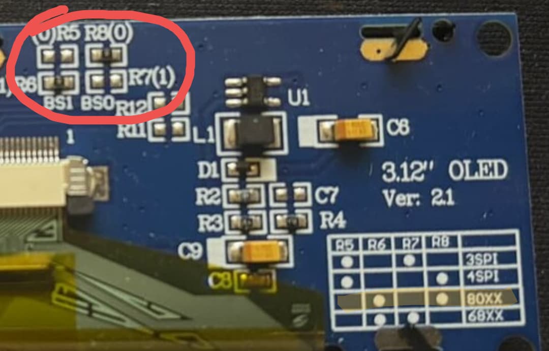
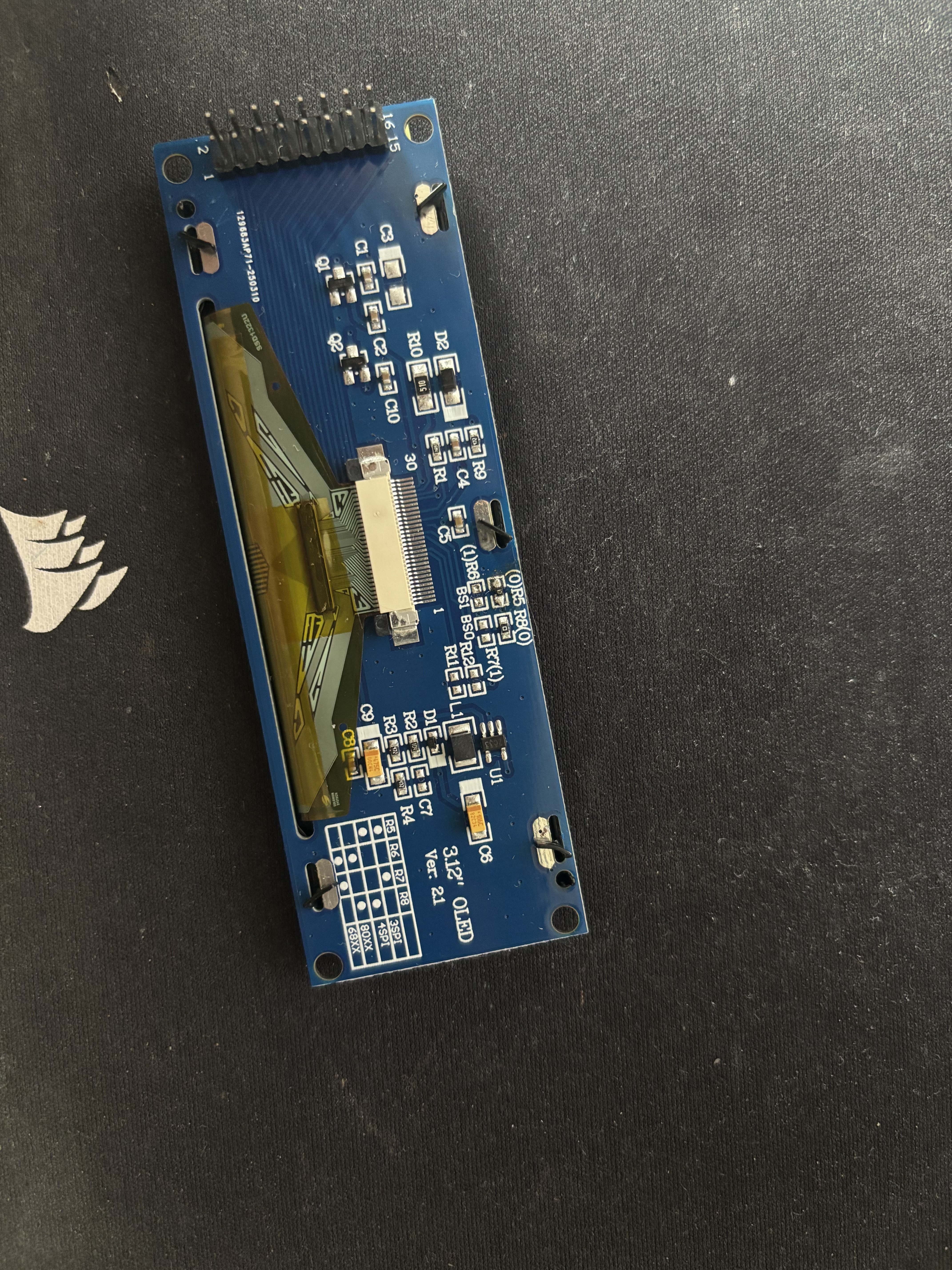
I checked with the multimeter and there's continuity between the 2 edges, so we should be good.
I'm going to reassemble my wiring and I'll let you know if I see any change.
If you had lost or damaged that resistor, you could simply put a large blob of solder across the pads. The 'resistors' are 0 ohms!
If you had not attempted to move the resistor, you could have complained to the seller, because it was described as SPI, but the board that was sent to you was not configured that way.
I must ask: why is your ESP8266 not plugged into your breadboard? That is the normal way.
Also your code is configured to use software SPI. If you can use the ESP8266's hardware SPI pins, the performance/update speed will be much better.
Thanks for your advice
To tell the truth, I've lost the resistance of the first screen so I'll try to connect the 2 dots like you told me. This will save me from throwing it away for nothing.
As for the hardware pins, I don't know which ones they are.
I'll find out
The "SW_SPI" says it's software SPI. There will be an equivalent "HW_SPI" constructor which will take fewer parameters because the hardware SPI pins are fixed so don't need to be specified.