I have a 24 led rgb ring about 4" in dia. I used the NeoPixel strandtest.ino on the arduino and it works fine, but when I program it to an attiny84 i get nothing. I can program the tiny to blink an led so i believe it is hooked up right.

Not a very useful photo. Can't even see a tiny84 there. Please post a schematic and your code, according to the forum guide.
The tiny84a is an smd verion and that black box is the socket, you have to zoom way in to see it. lol! I only have 6 wires going to the socket from the arduino for programming and i'm assuming it is connected right because i can program it to blink an led successfully.
Actually not much of a schematic to show, the ring has 4 connections in, out, 5v, and gnd. I'm only using the in and 2 power pins. i'm using the mosi pin as the input to the ring. (same pin i used to blink an led)
Strandtest is an example sketch by neopixel and i only changed the pin number to 5 and the number of leds to 24. And again it worked fine when i programmed it to the Arduino... Then i programmed it to the tiny84 and it was successful write, however the ring did not lightup at all.
Strandtest.ino
#if (F_CPU>7370000) //neopixel library required 7.37MHz minimum clock speed; this line is used to skip this sketch in internal testing. It is not needed in your sketches.

#include <tinyNeoPixel.h>

#define PIN 5

// Parameter 1 = number of pixels in strip
// Parameter 2 = Arduino pin number (most are valid)
// Parameter 3 = pixel type
//   NEO_GRB     Pixels are wired for GRB bitstream (most NeoPixel products)
//   NEO_RGB     Pixels are wired for RGB bitstream (v1 FLORA pixels, not v2)
//   NEO_RGBW    Pixels are wired for RGBW bitstream (NeoPixel RGBW products)
tinyNeoPixel strip = tinyNeoPixel(24, PIN, NEO_GRB + NEO_KHZ800);

// IMPORTANT: To reduce NeoPixel burnout risk, add 1000 uF capacitor across
// pixel power leads, add 300 - 500 Ohm resistor on first pixel's data input
// and minimize distance between Arduino and first pixel.  Avoid connecting
// on a live circuit...if you must, connect GND first.

void setup() {
  strip.begin();
  strip.show(); // Initialize all pixels to 'off'
}

void loop() {
  // Some example procedures showing how to display to the pixels:
  colorWipe(strip.Color(255, 0, 0), 50); // Red
  colorWipe(strip.Color(0, 255, 0), 50); // Green
  colorWipe(strip.Color(0, 0, 255), 50); // Blue
//colorWipe(strip.Color(0, 0, 0, 255), 50); // White RGBW
  // Send a theater pixel chase in...
  theaterChase(strip.Color(127, 127, 127), 50); // White
  theaterChase(strip.Color(127, 0, 0), 50); // Red
  theaterChase(strip.Color(0, 0, 127), 50); // Blue

  rainbow(20);
  rainbowCycle(20);
  theaterChaseRainbow(50);
}

// Fill the dots one after the other with a color
void colorWipe(uint32_t c, uint8_t wait) {
  for(uint16_t i=0; i<strip.numPixels(); i++) {
    strip.setPixelColor(i, c);
    strip.show();
    delay(wait);
  }
}

void rainbow(uint8_t wait) {
  uint16_t i, j;

  for(j=0; j<256; j++) {
    for(i=0; i<strip.numPixels(); i++) {
      strip.setPixelColor(i, Wheel((i+j) & 255));
    }
    strip.show();
    delay(wait);
  }
}

// Slightly different, this makes the rainbow equally distributed throughout
void rainbowCycle(uint8_t wait) {
  uint16_t i, j;

  for(j=0; j<256*5; j++) { // 5 cycles of all colors on wheel
    for(i=0; i< strip.numPixels(); i++) {
      strip.setPixelColor(i, Wheel(((i * 256 / strip.numPixels()) + j) & 255));
    }
    strip.show();
    delay(wait);
  }
}

//Theatre-style crawling lights.
void theaterChase(uint32_t c, uint8_t wait) {
  for (int j=0; j<10; j++) {  //do 10 cycles of chasing
    for (int q=0; q < 3; q++) {
      for (uint16_t i=0; i < strip.numPixels(); i=i+3) {
        strip.setPixelColor(i+q, c);    //turn every third pixel on
      }
      strip.show();

      delay(wait);

      for (uint16_t i=0; i < strip.numPixels(); i=i+3) {
        strip.setPixelColor(i+q, 0);        //turn every third pixel off
      }
    }
  }
}

//Theatre-style crawling lights with rainbow effect
void theaterChaseRainbow(uint8_t wait) {
  for (int j=0; j < 256; j++) {     // cycle all 256 colors in the wheel
    for (int q=0; q < 3; q++) {
      for (uint16_t i=0; i < strip.numPixels(); i=i+3) {
        strip.setPixelColor(i+q, Wheel( (i+j) % 255));    //turn every third pixel on
      }
      strip.show();

      delay(wait);

      for (uint16_t i=0; i < strip.numPixels(); i=i+3) {
        strip.setPixelColor(i+q, 0);        //turn every third pixel off
      }
    }
  }
}

// Input a value 0 to 255 to get a color value.
// The colours are a transition r - g - b - back to r.
uint32_t Wheel(byte WheelPos) {
  WheelPos = 255 - WheelPos;
  if(WheelPos < 85) {
    return strip.Color(255 - WheelPos * 3, 0, WheelPos * 3);
  }
  if(WheelPos < 170) {
    WheelPos -= 85;
    return strip.Color(0, WheelPos * 3, 255 - WheelPos * 3);
  }
  WheelPos -= 170;
  return strip.Color(WheelPos * 3, 255 - WheelPos * 3, 0);
}
#else //neopixel library required 7.37MHz minimum clock speed; these and following lines are used to skip this sketch in internal testing. It is not needed in your sketches.
#warning "Neopixel control requires F_CPU > 7.37MHz"
void setup() {}
void loop() {}
#endif
What volrage is the tiny84 running at?
Is there a bypas cap for the tiny84?
Update:
Hooking it up to a different laptop it is now lighting up! however it is all red and flickers strangely...
Btw there is 4.5vdc going to the tiny from the arduinos vcc, with a .1uf bypass cap.
I have a 1000uf cap and a 390 ohm resistor for the ring itself.
One thing i wonder is that... when im trying the ring out the arduino is still hardwired to the socket, so could there be feedback messing up the tiny while its working?
I'll make a schematic in the meanwhile.
thanks!
promocom:
Btw there is 4.5vdc going to the tiny from the arduinos vcc, with a .1uf bypass cap.
But what is powering the (which) Arduino? I see a Pro Mini with an unknown something connected to its programming header. ![]()
promocom:
I'll make a schematic in the meanwhile.
Better do so because so far it is totally confused! ![]()

You are using the ArduinoISP sketch? That changes the programming pins back to INPUT mode after uploading the sketch to the tiny, so there should be no interference when the tiny runs it's program.
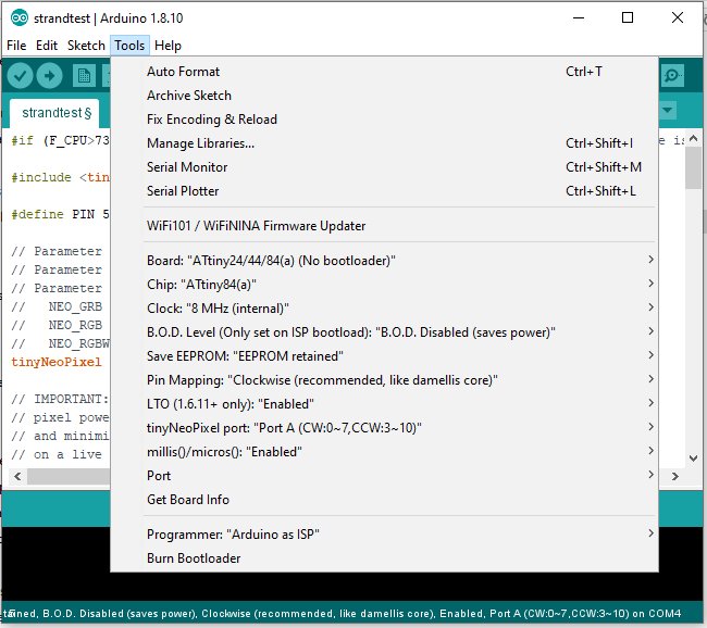
Are you running the tiny at 8MHz? They default to 1MHz out of the box. The sketch you posted will do nothing if running at 1MHz, and you should see a warning message when you verify or upload. So if not, set the clock to 8MHz internal and click "burn bootloader" before uploading.
Good to know i don't have to change the wiring... Yes its set to 8mhz and i burn a bootloader each time. I'm thinking i need to find a test program or a different simple sketch to see whats up. it seems when it starts up it begins lighting the leds in sequence before it goes all or partially red.
OK. Another difference is the library you are using. I'm not familiar with tinyNeoPixel. Can you run the standard NeoPixel strandtest.ino on the tiny?
Got it going! Even though it specifically said to use 8Mhz i tried it at 4mhz and that did it... thanks for you help!
I am surprised that it runs at 4MHz. Given that it does, can't think of any reason why it would not run at 8MHz. Have you tried going back and forth from 4MHz to 8MHz to confirm this?