Hello
i need to measure car rmp directly from a 3 wire sensor. 1) +5V. 2) Gnd. 3) Pulse 4.5 signal.
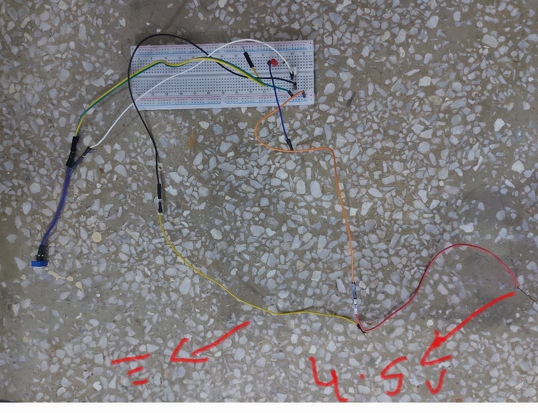
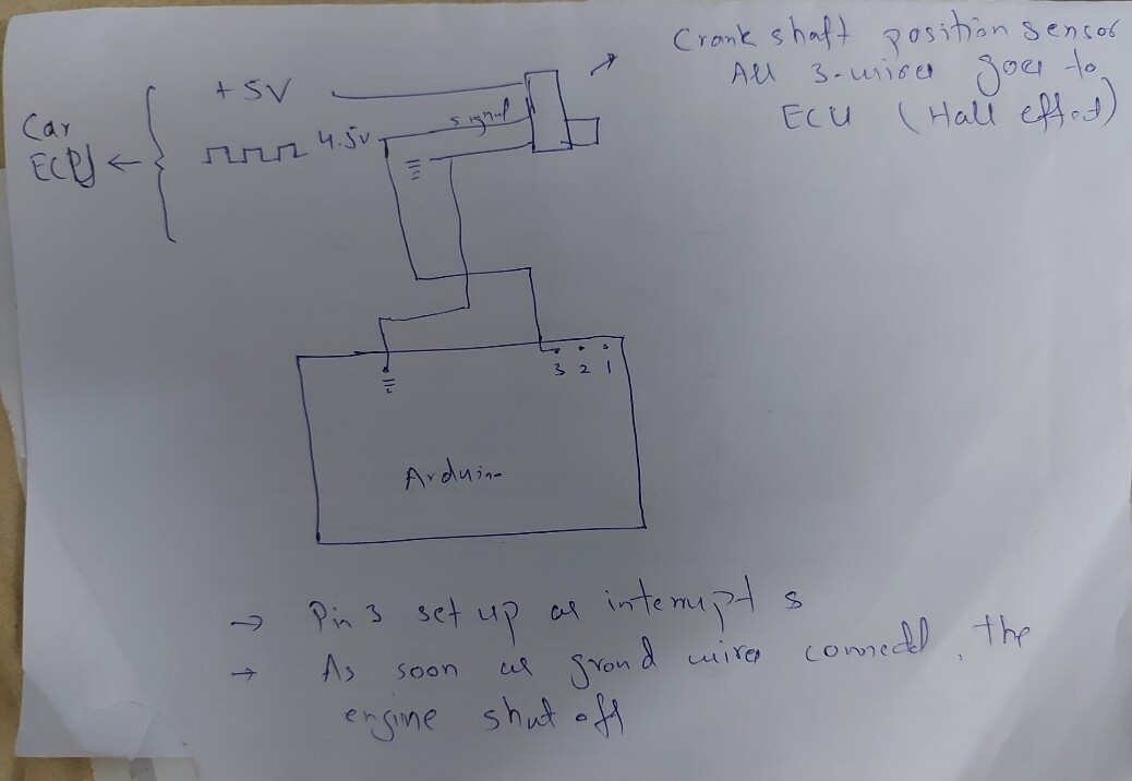
I need to count the pulse signal. when measuring pulse through arduino uno, i connect pulse signal of crank position (the 3rd 4.5v) to ardunio interrupt pin 2.
As soon as i touch the arduino ground pin to car ground, the engine stops everytime.
shat to do.
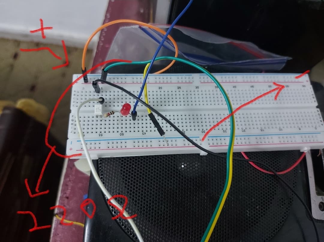
As a2nd experiment, i removed the arduino and simply connect a pc817 optocoupler with 220ohm resistance to Signal 4.5V. But as soon as i touch the 2nd (gnd) wire to car body, engine stops.
any help apperciated.
car is civic ferio 2003 with d16v1 engine.
It is doing what it was designed to do, when the crank stops it stops. You are basically shorting the sensor and without pulses the controller cannot run the engine as it does not know where the crank is. This can damage your system.
Post an annotated schematic showing how you have wired this, make notes on any wire over 25bm/10".
1 Like
Thanks, oh. never thought of that.
The drawing of both are attached. why does the arduino interrupt schematic shut off the engine.
Thanks.

It appears it is a VR (variable Reluctance) sensor. The ones I have worked with have a high impedance and will not supply much current. Following is a simple circuit that should work for you. Start by checking if the sensor ground is the same as the vehicle ground, if not stop.
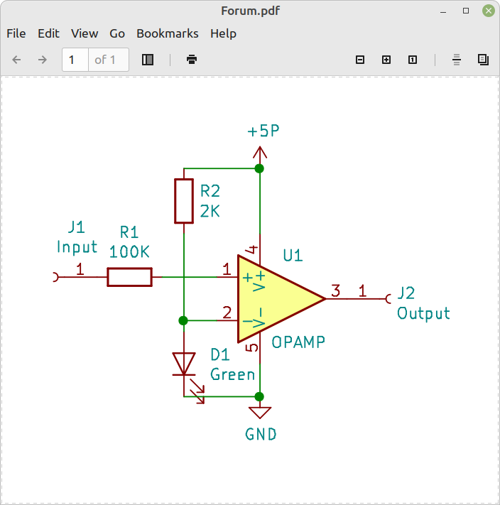
The LED is acting as a voltage reference (VF of LED) to bias the comparison point. The VR signal is fed into the input, the output is your signal. It is dependent on the op amp or comparator you chose. If you use a comparator you will need a pull up resistor. Do not power this from the ECM. I have used this circuit many times.
1 Like
Thanks a lot. Could you suggest Oamp or comparator Number please. Yes i checked car wiring diagram, ground is same as car body.
Thanks.
I have checked the forum with your key word Variable Reluctance Sensor and came up with 2 configuration. Credit goes to them for sharing the schematics.
I need to know which configuration is correct, because the 1M resistor wired are different in both schemes


. Thanks
If it has 3 wires and outputs a ~4.5V signal, then it is a Hall Sensor NOT a VR (Variable Reluctance) sensor.
Where does the Arduino get it's power?
Thanks Jim. Yes its 3 wire sensor. Presently i am testing so Arduino is powered from laptop usb.
In case, if it is Hall-effect sensor then previous post where Oamp is suggested to to couple with crankshaft sensor is still valid?.


The YEL/BLK wire is 5V feed from ECU, Blue is 4 or 4.5 signal wire and BRW/YEL is ground.
Thanks
I would suggest a simple N channel MosFet. Must be logic level compatible (or maybe not).
1 Like
No, not needed. However, I don't understand why connecting it to the Arduino makes the engine stop.
Connect the Arduno GND to the engine ground. Start the Arduino program. Make sure the input pin mode is set to INPUT. Connect a 1K resistor to the BLU wire, then connect the other end of the resistor to the input pin.
Should work.
1 Like
Thanks. i will connect 1k resistor to blue wire of vr sensor and other to ardunio pin setup as INPUT. And ground to ground. Dont you think its again shorting the singnal wire with ground of vr sensor through arduino. The ecu is very sensitive to vr sensor input and may detect short signal.
Thanks.
Thanks, could you suggest a circuit/ part no please.
No. The input of an Arduino has a very high impedance (resistance) in the range of several million ohms. The connecting wires need to be short, otherwise they may pick up interference from the spark plug wires.
Also I'm sure it's a hall sensor, NOT a VR sensor.
1 Like
I would think its more likely to be an inductive pickup. Engines run pretty hot and a hall would likely be $$ to be guaranteed to work at those temperatures.
I also have experienced some interference in the fuel injector operation when we tried to use it to measure RPM for a quick test. We even had a 10k or 100k resistor in series (its been some years).
1 Like
Before we try to design a circuit, you should do a test. I suggest you connect from your blue wire to ground some resistors:
- 1 Meg
if the 1 meg doesn't cause the engine to run rough or die then - 100k
and so on..... - 10k
- 5k
- 1k
This will tell us what resistive load the sensor can accept.
I don't know this but I suspect the signal coming from the sensor exceeds 5V. I also believe the ECU looks at the profile of this sensor and will shutdown if the profile falls out of the expected range.
1 Like
Thanks Jim. You mean the circuit is already connected/setup before powering up everything.
Nice suggestion, i will do that resistance test and teport back. Yes i heared without this crank sensor, some car dont start and other shutoff after 10 mnts.
Connect everything except the resistor to the arduino input pin and start the program.
Start the engine, then connect the resistor to the input pin.
pinMode(x, INPUT) Do not use INPUT_PULLUP
Maybe you should post your code here, so we can check