Apologies if this is the wrong section. I think it it's the closest related to what I'm doing though.
I've got two car related questions. First one isn't directly Arduino related but involves the ECU, second, I think I can do using relays only, but would be easier with an arduino or arduino type setup.
-
I'm installing electric radiator fans. I have a control module with a temperature probe and relays that have a resistor across the coil. there's an air conditioning wire I need to hook up so the fans turn on when it's active, but it also goes to the ECU as an input. Is the resistor across the coil enough to protect the ECU or should I hook up a third relay with a diode to be sure?
-
I'm going to be swapping engines later this year and the current ECU is going to go away. Currently there's three pressure switches that go to inputs on the ECU to monitor for air conditioning compressor activation. What most people do on engine swaps in these cars is to just wire those three switches in series to the compressor relay. However, I'd like to use them as inputs to an arduino or PLC and have LED indicators for each switch, but I've also read that arduinos do not like to play nice with vehicle electric systems due to noise and spikes and whatnot. I think I can do it using just relays, but that could get bulky. Is there an arduino like PLC more suited for vehicle applications?
Hello jimdaug
Welcome back 
Take a view and check the CERTIFICATE OF COMPLIANCE.
Whooo that's a little pricey.
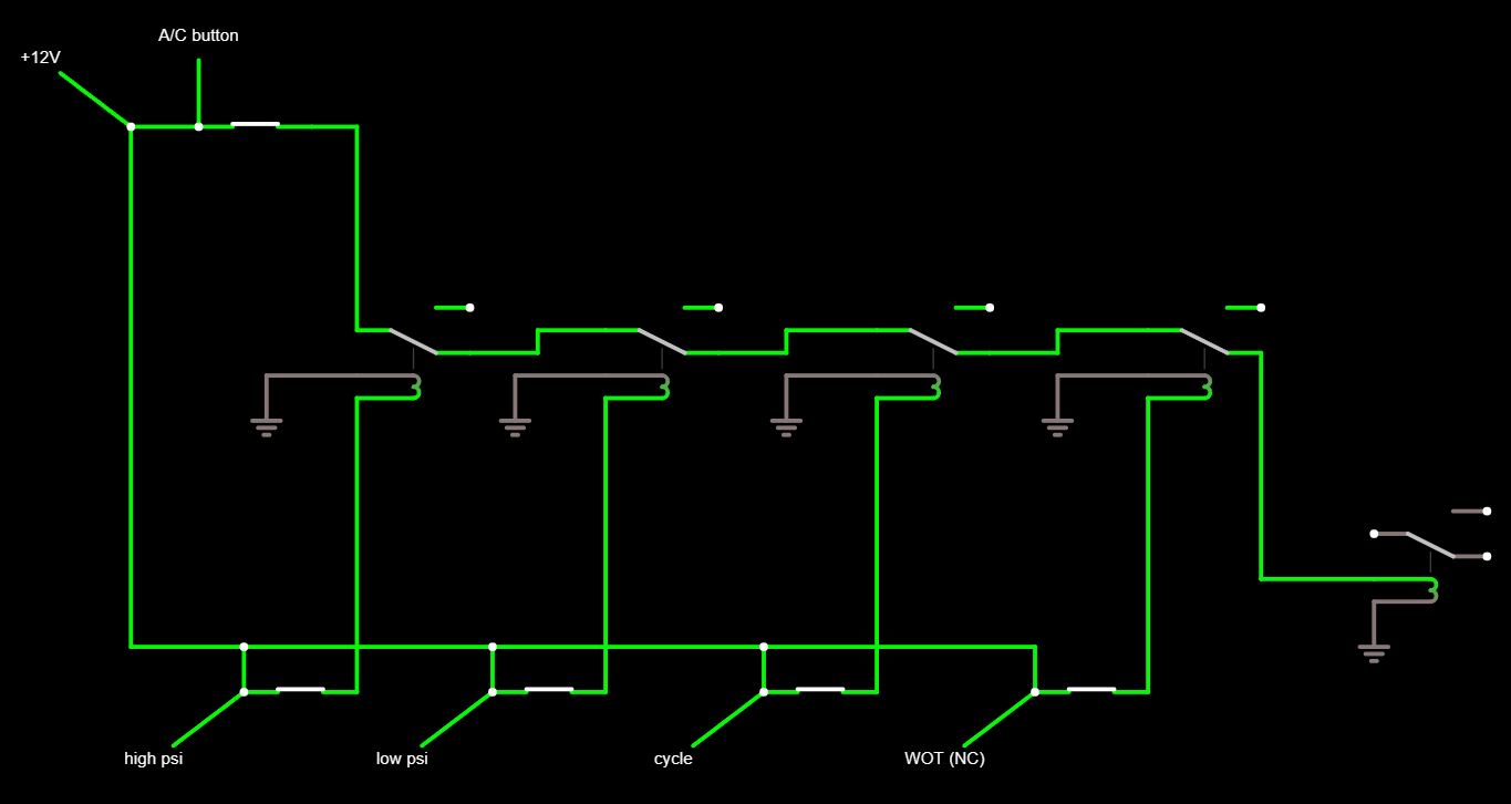
I'll probably stick with the relay chain. Here's what I've got going so far. I found relays that have an LED indicator when activated and I'll need to find a circuit that lights when one of the switches is open to show a fault.
Any thoughts on the first one?
I would not recommend an Arduino especially for under hood as your application appears to be, that is a 125C environment. The electrical environment in a vehicle is very bad and you will have to take additional precautions to protect the Arduino.
You should have a flyback diode. I don't know why there is a resistor unless it has another purpose. The control module probably has a diode inside.
For on-off "digital" inputs you can add a Protection Circuit to protect against 12V, or higher spikes, and negative voltages/spikes. (You can increase the current-limiting resistor to between 1K and 10K.)
For analog inputs you can use a Voltage Divider and it's still a good idea to add the protection diode(s). Of course, you can also use the voltage divider with digital inputs... It's just one more resistor added to the protection circuit.
If you need to boost the outputs to 12V, or if you need more than a few milliamps, (including if you want to drive a relay coil) you'll need a Driver Circuit. Or for relays there are "relay boards" with a relay driver and relay.
Resistors are commonly used for coil suppression on automotive relays. The reason is that they allow the field to collapse faster than a diode and therefore break the contacts faster and prevent contact erosion better. The tradeoff is a higher voltage transient than with a diode and this is handled instead in the ECU.
EmilyJane replied while I was typing.
From what I've read, it's supposed to do a similar job to the flyback diode but isn't polarized and isn't as good as the diode would be.
Davies Craig who makes the module also sells replacement 24v relays for different applications so they should be replaceable. I didn't have any luck just pulling on them so they may require a gentle prying. If that's the case then I should be able to replace them with integrated diode relays after double checking the polarity which seems like the safest way to go since I don't have a clue what the circuit is like inside the ECU. I would hope it's protected, but who knows and I'm just a newbie still so I probably wouldn't even know what I was looking for if I tore it open.
As for the voltage dividers and drivers, like I said I'm still new enough at this that they're hard for me to grasp. Harder than simple relays and software code anyway. So for the time being I think it's safer to stick to the relays.
You could look at the data sheet for your factory installed relays. If they have the resistor then you can be pretty certain that the ECU is protected. If a relay is in a service with a high duty cycle, you might save yourself a lot of relay replacements.
They're not factory. They are on a universal fan control module I bought. The existing wire I'm splicing into goes from the a/c switch in the cab to the ECU.
It does bring up another question or two though. I can't visually verify which polarity the relay coil is wired on the module. It's just a socket on a potted in board. It's got a temperature probe and led segment display and hook up wires for ignition hot, battery hot, fan +12 and A/C trigger.
They're showing to splice into the clutch power wire, but to me it makes more sense to tap into the a/c button since it's going to be a constant signal and not cycle with the clutch.
I got some diode protected relays from Amazon and I tested one just putting the coil wires on the battery terminals and it triggers in either polarity, but did I kill the diode when I hooked up in reverse? (EDIT: From more reading I think I probably did.)
I was thinking it wouldn't trigger in reverse polarity, but the diode is in parallel to the coil so I don't know why I was thinking that. And how would that apply if the sockets on the fan module are in reverse polarity? It wouldn't matter with a resistor, but would it still work and just not provide any protection? Is there any simple way to test for a spike or verify the diode is working properly?
I guess that's about four questions lol.
Thanks
Hello,
For the electric radiator fans, using a resistor across the relay coil should offer sufficient protection for the ECU, though adding a third relay with a diode could provide extra assurance against voltage spikes. Regarding the engine swap, while Arduino boards may be sensitive to vehicle electrical noise, you can address this with shielding and filtering techniques. Alternatively, consider using Arduino-compatible microcontrollers designed for automotive use, like those from Arduino's MKR series, or dedicated automotive-grade PLCs for robust performance in vehicle applications.
I realize that. I'm talking about any OEM relays that might have come with the vehicle from the factory. What type of suppression they use will be safe for the factory ECU.
I did some poking with my multimeter and discovered that the socket terminals 85 and 86 for the coil do not have continuity with the Ignition+ or ground wires. I'm thinking that means it's transistor controlled?
When I get a chance I'm going to hook it up without the relays and heat up the temp probe with a heat gun and see what voltages I get on those terminals. I'd still like to test that A/C wire for voltage spike if there's a simple way to do that.