hey,
does anyone have a clue on the pinout of this casette tape head. i plan to replace this with an aux signal so i can plug my phone into my car. (which is obviosly pretty old)
-8 pins on physical head
-4 wires leave on one side
-other 4 are connected together to one wire
The "wires" you refer to are actually traces on a flexible printed circuit board. But there is actually an easier way to do what you are proposing. Many years ago people used the cassette tape player in their car as an audio amplifier/speaker system, just like you are suggesting. They opened up a cassette tape cartridge and took all the tape out and the wheels and all the drive/take up wheels. Then they wound a small coil of magnet wire and put it in the cartridge so the coil would be resting on the read head when inserted into the player.
The coil ends were connected to the speaker output of their radio, or what ever was supplying the audio. The coil induced a signal into the tape read head and there was the audio playing through the car speaker system.
There was a commercial version of the same tape cassette and functioned the same way. Just looked a lot nicer.
I have never made such a conversion, so my offering to you is about all I can help with.
Paul_KD7HB:
The "wires" you refer to are actually traces on a flexible printed circuit board. But there is actually an easier way to do what you are proposing. Many years ago people used the cassette tape player in their car as an audio amplifier/speaker system, just like you are suggesting. They opened up a cassette tape cartridge and took all the tape out and the wheels and all the drive/take up wheels. Then they wound a small coil of magnet wire and put it in the cartridge so the coil would be resting on the read head when inserted into the player.
The coil ends were connected to the speaker output of their radio, or what ever was supplying the audio. The coil induced a signal into the tape read head and there was the audio playing through the car speaker system. Otherwise you have to figure out how to turn the audio signal into something that looks like the signal from a tape head, so the circuitry will turn it back into a recognizable audio signal.
There was a commercial version of the same tape cassette and functioned the same way. Just looked a lot nicer.
I have never made such a conversion, so my offering to you is about all I can help with.
Good luck!
Paul
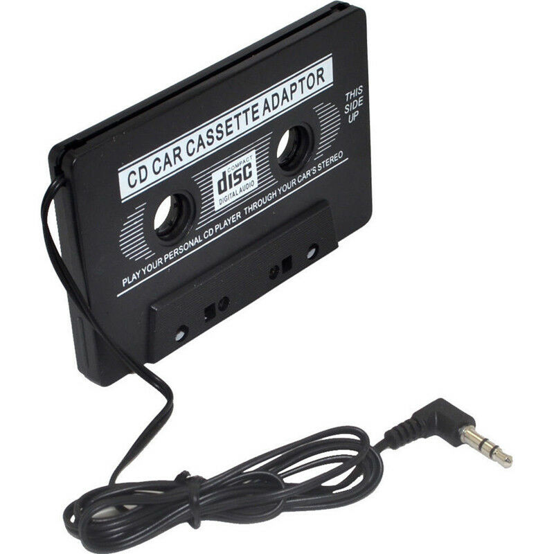
These devices are (or were, at least - maybe not so much anymore) readily available to play audio from portable devices in cars with a cassette deck but no aux in.
doing the mod you described would be easier if you were to trace out the circuit and inject your signal after the circuitry that converts the signal from the magnetic tape head into a normal audio signal.
DrAzzy:
doing the mod you described would be easier if you were to trace out the circuit and inject your signal after the circuitry that converts the signal from the magnetic tape head into a normal audio signal.
yeah im gonna try that ig and then if i cant get the pinout to the main board after reverse engineering it (it has like 18 pins just for the casset circuit connection) and then if i cant get that ill do what paul said
do u know y there might be so many pins?
i would think it would only need the left and right and a few pins so say when to control the motors...
i dont really want to do the adapter because i already spent a long time taking it apart and i dont want to put it all back together for nothing lol idk
also i want planning on making it more permanent (though i guess it doesnt really matter)
I hope you realize that the output of
that tape head may be only as much
as one millivolt RMS. The confusing
thing is that there only needs to be
4 pins on the tape head: 2 for left
and 2 for right channel.
im gonna figure out the wires that go out to the speakers in the car then work backward to find the audio channel from the caseet circuit because one of the ics doesnt have a readable label on it
The frequency response of the preamp of the playback head is not linear.
You could have lots of bass and little or no highs.
Try to inject your aux signal somewhere at the output of the head preamp.
Leo..
im gonna figure out the wires that go out to the speakers in the car then work backward to find the audio channel from the caseet circuit because one of the ics doesnt have a readable label on it
The volume control pot is usually a good place to tap-in. But you should disconnect the existing circuits (or a add a switch if you still want to use the radio) so you're not "back-driving" the internal preamp, and that will also eliminate any noise from the preamp.
-8 pins on physical head
-4 wires leave on one side
-other 4 are connected together to one wire
If that's an auto-reverse deck you probably have 4 coils (in one head/housing). 2-wires each with one grounded.
Looks like a 4-track head. Very ancient. Use a DVM to verify my thesis. The one row with all the pins bridged together is ground, and the other four go to a winding in the head.
You can use a standard audio amplifier. Connect each of the four pins, one at a time to the left-in on the amplifier. Cover the head gaps with a thick piece of paper to protect it, then tap a magnet (weaker is better) on the head. Your amplifier should give a loud pop. If I am right that it is a 4-track head, then all four pins would produce an audio pop from a magnet.