I’m a electronic novice and don’t want to blow up my Arduino Uno 3, so I loaded this seemingly simple project into Tinkercad.
The project is a Chair Occupancy switch that turns on a reading light when someone is in the chair. The light is a small panel of leds powered by a 12vac wall adapter.
I planned on powering the Arduino with a 5 volt wall adapter and running the 12v through a Mosfet to power the lights. In Tinkercad, no matter what I do, the simulation turns on the lights as soon as I start the simulation. The seat sensor (simulated with a pushbutton switch) works fine both on the simulator and when I breadboarded it with the actual seat sensor.
I’m obviously doing something wrong.
Here’s the Tinkercad image. The reading light voltage is simulated by a 9 volt battery and the digital light panel is shown as a DC motor. (the actual components weren’t available in Tinkercad.)
Also here’s the code. I got most of the code from a closed post here - https://forum.arduino.cc/t/pressure-sensor/546144/4. I don’t understand the “!digital Read(switchPin)” but it worked great on the breadboard. I didn't know what kind of data type or value my seat occupancy switch was returning so I tried to capture it and display in the serial monitor. I was surprised to see a value of 1 when not pressed and 0 when the button was pushed.
// from arduino forum  https://forum.arduino.cc/t/pressure-sensor/546144/4
// using sensor that looks like mine

const byte switchPin = 2;  // connect the switch to pin 2, the other side to ground
const byte ledPin = 13;  // use the built-in LED as an indicator
const byte LightsPin = 3; // this pin sends signal to Mosfet to turn on lights
byte SwitchRead; // variable to store value of the Seat Occupancy Switch

void setup() {
  pinMode(switchPin, INPUT_PULLUP);
  pinMode(ledPin, OUTPUT);
  pinMode(LightsPin, OUTPUT);
  Serial.begin(9600);
}

void loop() {
  digitalWrite(ledPin, !digitalRead(switchPin));
  digitalWrite(LightsPin, !digitalRead(switchPin));
  SwitchRead = !digitalRead(switchPin);
  Serial.println(SwitchRead);
}
How will the D3 output pin signal return back to the controller?
Why are not the recommended resisors used with the controller and the transistor?
Exactly which transistor is used?
here some information regarding the line you do not understand with just a little change in the sketch:
// from arduino forum  https://forum.arduino.cc/t/pressure-sensor/546144/4
// using sensor that looks like mine

const byte switchPin = 2;  // connect the switch to pin 2, the other side to ground
const byte ledPin = 13;  // use the built-in LED as an indicator
const byte LightsPin = 3; // this pin sends signal to Mosfet to turn on lights
byte SwitchRead; // variable to store value of the Seat Occupancy Switch

void setup() {
  pinMode(switchPin, INPUT_PULLUP);
  pinMode(ledPin, OUTPUT);
  pinMode(LightsPin, OUTPUT);
  Serial.begin(9600);
}

void loop() {
  // The byte variable SwitchRead is set to HIGH or LOW depending
  // on the state read by the function digitalRead(switchPin).
  // The exclamation mark (!) in front of a (usually boolean) variable
  // is inverting the result of digitalRead(). If the result was HIGH it becomes LOW
  // or vice versa.
  // As switchPin has been set to pinMode INPUT_PULLUP the return of digitalRead()
  // will be HIGH if the button is not pressed (the switch is open) as an internal pullup
  // resistor keeps the input state on HIGH level.
  // If the button is pressed, switchPin is connected to GND. This draws the state
  // to LOW.
  // To make sure that the Led and the Light are switched OFF when the button is
  // not pressed, the state has to be inverted:
  //
  //  See this table of states
  //
  //    Switch                 Switch state        Light state
  //  -----------------------------------------------------------------
  //    not pressed              HIGH                   LOW
  //    pressed                  LOW                    HIGH
  //
  //
  // As loop() loops really quick (not to say damned quick) it is sufficient to
  // read the switch state once per loop and use the variable to set ledPin
  // and LightsPin.

  SwitchRead = !digitalRead(switchPin);

  digitalWrite(ledPin, SwitchRead );
  digitalWrite(LightsPin, SwitchRead );
  Serial.println(SwitchRead);
}
Hope that explains what !digitalRead() is used for ...
I was surprised to see a value of 1 when not pressed and 0 when the button was pushed.
It depends on
whether you used digitalRead(SwitchPin) or !digitalRead(SwitchPin) and
if your switch is "normally open" or "normally closed" meaning whether it shortcuts the terminals when pressed or disrupts the connection when pressed.
If in doubt use an Ohmmeter to find out about your switch...
Nice start, close but it will not work. You are using a N-channel MOSFET which is the correct part but you have it connected improperly but it is close. The battery - goes to the Source of the MOSFET not the +. In your case simply reverse the + and - connections.
Note the MOSFET uses the source as its reference point which would be correctly connected to the - of the battery but it also needs to be connected to the ground of the Arduino. If you are using the internal pull up resistor and the button does not work rotate it 90 degrees. You will see in this forum many times connect the grounds.
If you want a real CAD (Computer Aided Design) package download KiCad, they ask for an optional donation. Many of us use it, it will take us from schematic capture through printed circuit boards. It will take some time to master but after that // o //.
Thank you. That link you gave me is interesting and going to take me some time to digest :). Thank you. Adding to my education, I'll have to learn more about reading schematics to this new electronics dbbling I seem to be drawn to.
Good q about the wall adapter. It does output 12v dc. So thankfully I've got that right.
I didn't understand the part about a return path to the Arduino. But the next responder cleared that up for me.
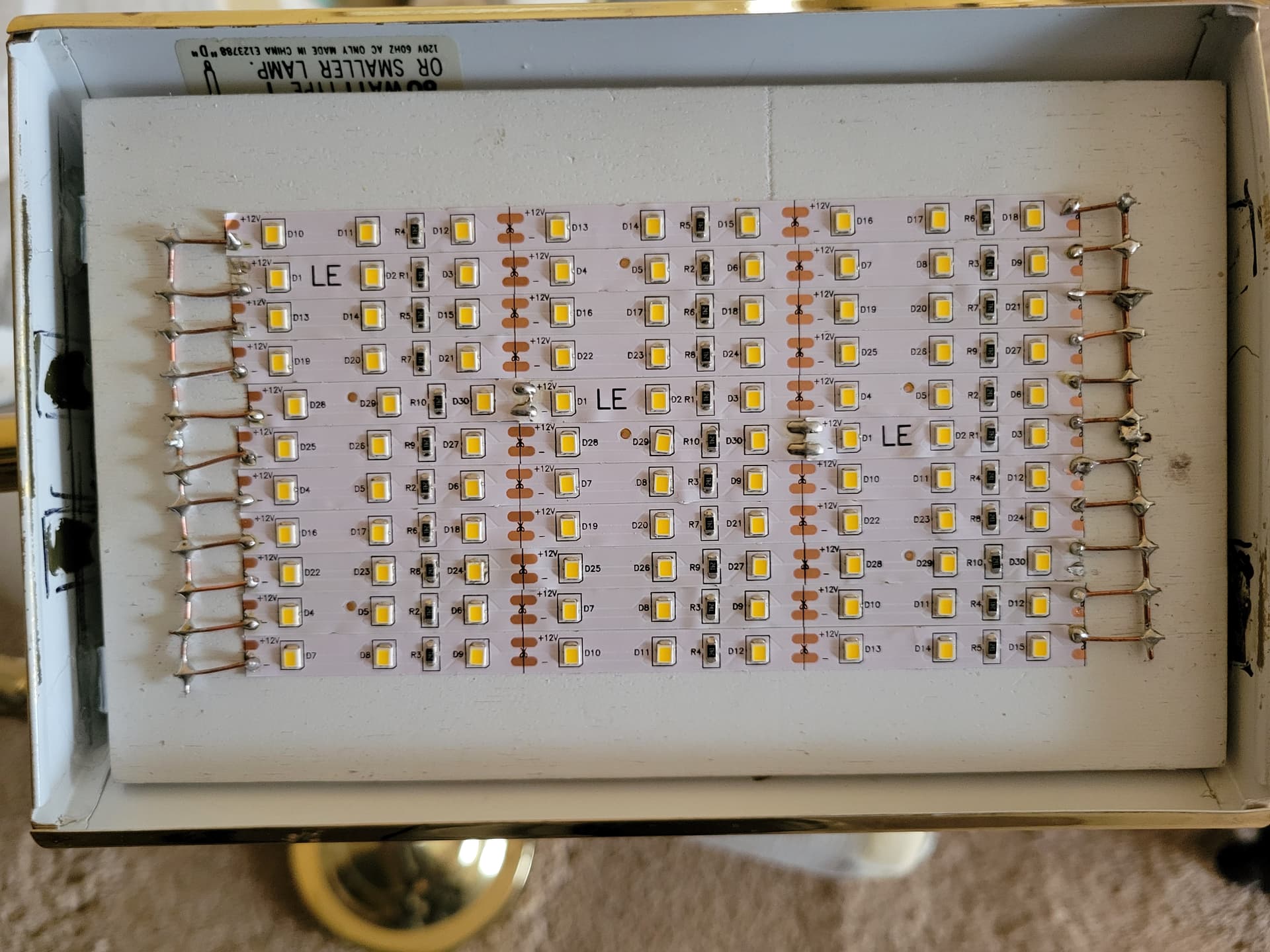
I guess I should have included info on my LED light panel at the start of this whole conversation. Apparently the strips I used to constuct it already have the requisite resisters built in. I've been using this light for several years now without a problem. Here's an image of the light panel.
Electricity tells rhe transistor to turn ON, but for that to happen, the transistor has to know it’s being turned on.
Voltages are ‘relative’ to some other point in the circuit… e.g, a +5V pulse, is -7V if the reference is +12V,,.
The transistor needs to know what the (Gate) signal is relative to (the Arduino ground (0V)), so the gate voltage needs a path back to 0V so the transistor can light up the S-D path,
I have not worked with Tinker, so I cannot compare.
Wokwi has some nice capabilities, especially the built-in examples if you add a device and the examples that make it easy to start from. The possibility to add a link to a certain Wokwi project in the forum is a great feature. Providing a "working solution" eases to assist other members.
Wokwi is quite realistic in a lot of cases, some features still lack (e.g. if you create a resistor ladder (see https://en.wikipedia.org/wiki/Resistor_ladder) it will not be handled correctly by analogRead(). Still waiting for someone who further develops this ...
If you want to improve I suggest to buy a book about C++. There are also online references and tutorials but sometimes the good old fashioned book is better. For a certain time you can read and try to understand without being distracted by a keyboard ...
And I forgot to respond to your "Have fun" comment earler. That's exactly what this is. FUN trying ot understand something so new to me. It's a fun curiosity still while struggling to grasp some of these concepts. Thanks for the encouragement.
Success! thank you all. 15 second video of results. While simple stuff for you all, as a newbie, it's totally amazing to me to be able to create this (with all your help)! [https://youtu.be/hQRa-Z1fmtk?si=DF2FpD8eo5i4yFrY]
Now on to making this a real permanent item. I've got alligator clips, jumper wires, and a lot of space taken up with the breadboard and Arduino. With only 1 input, and two output ports of the Arduino Uno used, and not looking to put into production, there's got to be a more economical way to finalize this. I'll start a different topic for this next stage.
If you want to make it smaller, you can design a dedicated PCB and let that be produced. You can design around a SparkFun Pro Mini or Arduino Nano.
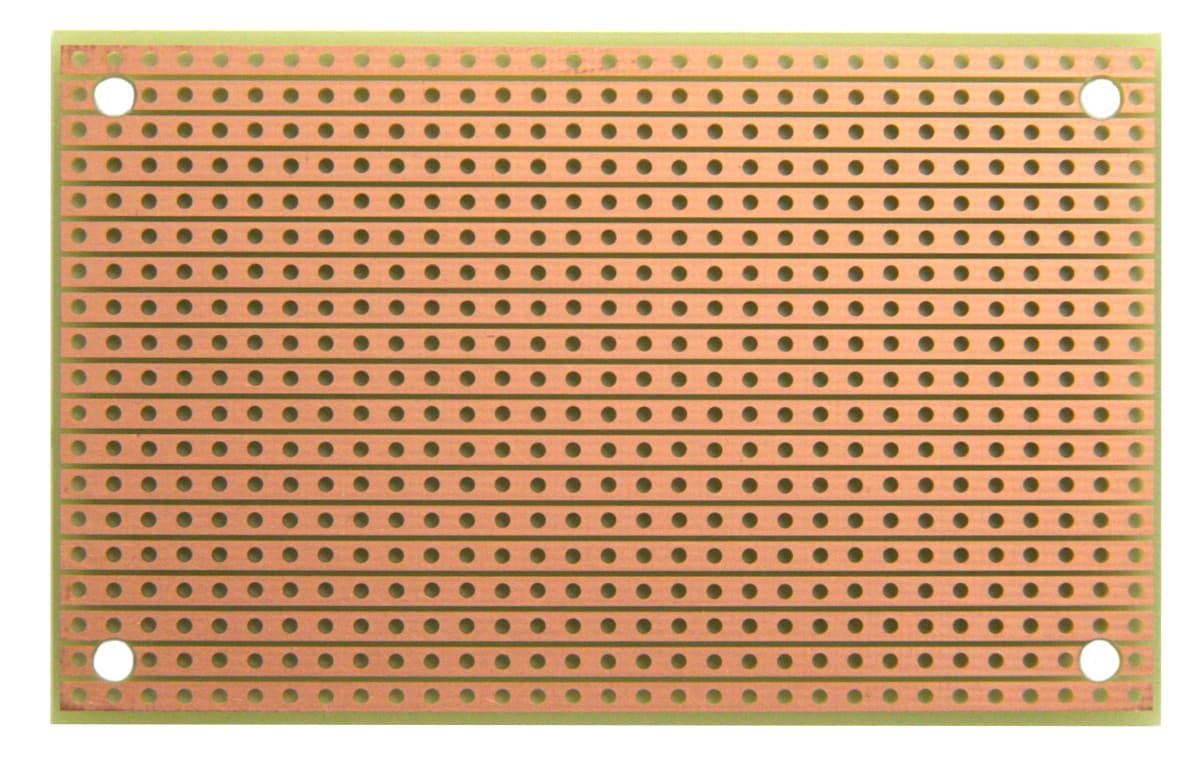
Alternatively you can use some strip board like below (just one of the first images that I could find; ST1 | StripBoard-Size 1 | BusBoard Prototype Systems) and solder your stuff on; I would advice to us a socket for the Nano or Pro Mini so it can easily be replaced.
Oh for sure, Got to make it smaller and permanent. I started a different topic on how to take this project to final hardwired device. Over there they recommended Nano, so that's what I ordered. [Making Breadboard Project into final device]
I looked at a video this morning on creating a PCB using Fritzing. But I only need one. So I think I'll be soldering wires and components on a strip board like you show. Like your idea of using a socket. I'll have to find out how to do that.
Learning a lot here, trying not to get overwhelmed, AND 'having fun.