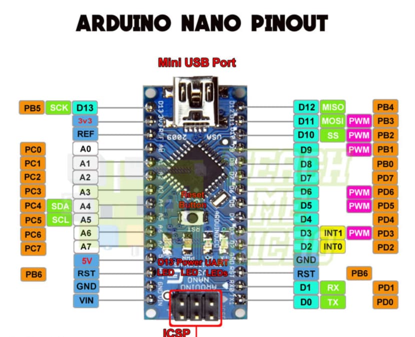
The idea of this project is to recover wasted heat from the exhaust of a Chinese diesel heater in my off grid shed using a water filled heat exchanger, water pump, motorcycle radiator and a radiator fan. I have 3 DS18B20 type temperature sensors connected to pin 4 of my Nano with onewire. Sensor 1: room temp. Sensor 2: heat exchanger temp. Sensor 3: radiator temp. Also connected to the nano on pins 2 and 3 (both PWM) is 2 PC817 optocouplers driving 2 mosfets for brushless motor speed controllers (pump and fan). The program is supposed to work by reading the temps from the sensors then adjust the pump and fan speeds accordingly at 1 minute intervals to prevent ware on the motor bearings from constant acceleration and deacceleration. My code works in this format with timers as float s however if I use the timers as an int eg. int startmillispump = millis(); it enters the If timer statement 4 or 5 times when it should only enter once until the 1 minuet time has expired. Can someone explain why it would do this please. Many thanks Steve ( I'm a hacker trying to be a bit better)
/*
pin 4 3 temp sensors
pin 3 pump via optoisolator and mosfet
pin 2 fan via optoisolator and mosfet
pin 5 use an optoisolator power switch for PSU
*/
#include <OneWire.h>
#include <DallasTemperature.h>

#define ONE_WIRE_BUS 4
OneWire oneWire(ONE_WIRE_BUS);
DallasTemperature sensors(&oneWire);

float room;  //room temp
float egr;   //egr temp
float rad;   //radiator temp

const int setpoint = 30;
const int pump = 3;
const int fan = 2;

/*off timer
int startmillis = millis();
int currentmillis = millis();
int offtimer = 1200000;
int offswitch = 5;*/

//pump/fan
float startmillispump = millis();
float currentmillispump = millis();
float startmillisfan = millis();
float currentmillisfan = millis();
float time = 60000;

void setup() {
  Serial.begin(9600);
  sensors.begin();

  currentmillispump = millis() + time;
  currentmillisfan = millis() + time;

  pinMode(fan, OUTPUT);
  pinMode(pump, OUTPUT);
  //  pinMode(offswitch, OUTPUT);

  digitalWrite(fan, LOW);
  digitalWrite(pump, LOW);
  //  digitalWrite(offswitch, HIGH);
}

void loop() {
  sensors.requestTemperatures();  // Send the command to get temperatures
  room = sensors.getTempCByIndex(0);
  Serial.print("Room Temperature: ");
  Serial.println(room, 2);
  //----------------------------------------
  egr = sensors.getTempCByIndex(1);
  Serial.print("EGR Temperature: ");
  Serial.println(egr, 2);
  //----------------------------------------
  rad = sensors.getTempCByIndex(2);
  Serial.print("Radiator Temperature: ");
  Serial.println(rad, 2);
  //----------------------------------------
  Serial.println("=========================");
  //delay(5000);  //test interval

  //switch the pump on 50% if egr temp is 10 degrees higher than room temp and less than 30 degrees
  if (currentmillispump > (startmillispump + time)) {
    if ((egr > (room + 10)) && (egr <= setpoint)) {
      analogWrite(pump, 125);
      startmillispump = millis();
      //startmillis = millis();
      Serial.println("pump below 30 degrees");
    } else if ((egr > setpoint) && (egr <= (setpoint + 10))) {
      analogWrite(pump, 180);
      startmillispump = millis();
      //startmillis = millis();
      Serial.println("pump between 30 - 40 degrees");
    } else if (egr > (setpoint + 10)) {
      analogWrite(pump, 255);
      startmillispump = millis();
      //startmillis = millis();
      Serial.println("pump over 40 degrees");
    } else {
      analogWrite(pump, 0);
      //currentmillis = millis();
    }
  }
  /*if (currentmillisfan > startmillisfan + time) {
    if (rad > (room + 10) && (rad <= setpoint)) {
      analogWrite(fan, 125);
      startmillisfan = millis();
    } else if ((rad > setpoint) && (rad <= (setpoint + 10))) {
      analogWrite(fan, 180);
      startmillisfan = millis();
    } else if (rad > (setpoint + 10)) {
      analogWrite(fan, 255);
      startmillisfan = millis();
    } else {
      analogWrite(fan, 0);
    }
  }
  //off timmer
  if (currentmillis > startmillis + offtimer) {
    digitalWrite(offswitch, LOW);
  }*/
  currentmillispump = millis();
  currentmillisfan = millis();
}
sorry that should be pins D2 and D3 both are PWM but that is not the issue. My question is why a float on my timer using millis() will work properly but a int with millis() does not, using int it enters the if timer statement 4 or 5 times in a couple of seconds ( see my code under //pump/fan in the global setup). My understanding is a float is a decimal point number and a int is rounded to a whole number
You have to use an unsigned long. You also have to code to defend against wrap-around, when the unsigned long hits its maximum value and resets to zero.
I think it will be worth it as the fan on the heater draws around 100w on full power and the exhaust gets around 200C so recovering the heat from the exhaust with a pump and fan running around 20w should save on diesel and 12v battery. With this configuration the heater should run less on full power that's the theory anyway.
that is the 50 day thing right? the bottom of my code is a timer currently commented out // to shut the whole system off after 20 minuets of inactivity so shouldn't run into these problems
Better check on things, again. The amount of Diesel is always the same volume per second/minute as long as the pump is on. Your results will be the same as if you just turned the thermostat temperature setting down.
my diesel pump is set at 0.8Hz low delivering 0.0176ml per second and heating the exhaust around 60C on high setting it is at 3Hz delivering 0.066ml per second and the exhaust running around 200C if I can get most or some of the heat disappearing out the exhaust heating outside back into the shed the diesel heater will be running more time on the low setting definitely saving diesel and hopefully saving some battery power too.
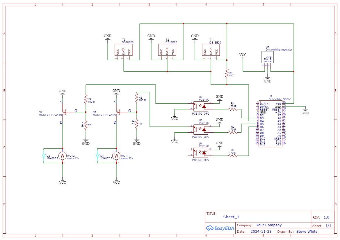
I'm using IRFZ44N power mosfet s although they start turning on at 4v I'm using the optocouplers so I can drive them between 11v - 13v (dependant on my battery state) so they are fully on and do not cause heat though resistance. I'm protecting the PC817 from surge with a 100 ohm resistor to the gate then a 10K resistor to ground to discharge. So the drive voltage is between 10.9v - 12.9v
I've got that covered at the bottom of my code there is //off timer this activated after 20 minuets of inactivity and is connected to another optocoupler via D5 to drive another mosfet for the whole system.
Can you please post a copy of your circuit, a picture of a hand drawn circuit in jpg, png?
Hand drawn and photographed is perfectly acceptable.
Please include ALL hardware, power supplies, component names and pin labels.
Hi Tom, you are right unfortunately the image I looked at for pin out is wrong I have now updated my schematic so now using pins 3, 5 and 6 as outputs. The motors and fly back diodes are undecided at his moment but will be around 1amp. VCC is 12v lead acid battery so voltage can vary up to 14v when charging hence the switching 5v. U4 is unconnected but will go to something like a SSR that will act as a latch circuit to disconnect the Nano and diesel heater from the battery with a push button to start the system.
Hi,
Thanks for the schematic.
The output of the 5V regulator should go to the 5V pin of the Nano, not Vin.
Vin is the input to the Nano's own 5V linear regulator, so the output of the linear reg will be less than the 5V logic needs.