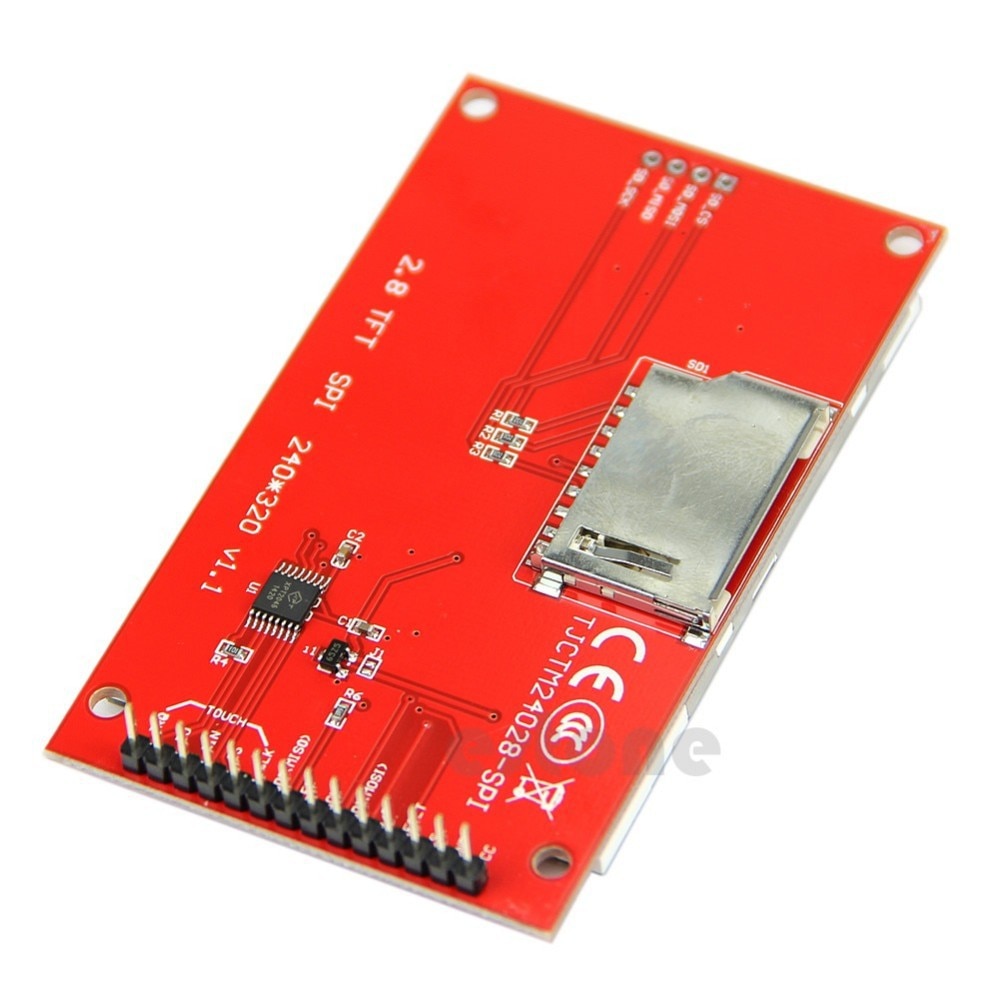
Thanks David, the last pictures are the display that I have. So the touch should work.
How did you make it work ? What wiring and what libraries ?
I use a nano, if this can help.
Personally, I put TFT, SD, XPT2046 all on a 3.3V SPI bus. With 3.3V TFT_CS, TFT_DC, TFT_RST, SD_CS, XPT_CS signals. i.e. seven 3.3V outputs and one 3.3V input (MISO)
There is no need for any level shifting because I always use 3.3V Arduinos e.g. Seeeduino, Zero, Due, STM32, Teensy3.2
Yes, you can use resistors, potential dividers or special purpose chips to achieve the level shifting.
What is the attraction of a Nano? It is cheap. So is a STM32 BluePill or MapleMini.
I prefer to use target with Arduino headers. So I can swap hardware with ease.
David.
Edit. What is really interesting: how did an inaccurate photo get posted in #0 ?
I have exactly the same 2.8" SPI touch screen (as in your later picture) with XPT2046 touch controller chip.
I used this to get started. If you have the tft part wired and working, the touch panel requires only one more Arduino pin for the chip select (T_CS).
In the mean time I have gone on to develop my own calibration code using only 2 points to match accurately the coordinates of the touch screen with the tft display.
I ran the example on my Seeeduino board. (3.3V Uno )
It works fine.
Obviously my SCK, MOSI, MISO are on 13, 11, 12. Same as a Nano. But I don't have to worry about level shifting.
Note that any unused SPI devices must be unselected. e.g. external pullup or specific digitalWrite() from your program. You can only select one SPI device at any one time.
You're lucky, I really don't understand why it's not working for me.
I double checked and saw that I had the interrrupt wired on D3, do I changed to D2 but it's still the same : infinite loop saying "Pressure = 4095, x = 0, y = 0"... even if I don't touch it
When I use it just for display, I use this :
#define _sclk 13
#define _miso 12 // Needed for SD card, but does not need to be connected to TFT
#define _mosi 11 // Master Out Slave In to send commands/data to TFT and SD card

// TFT chip select and data/command line
#define _cs 10
#define _dc 9

// SD card chip select
#define _sdcs 8

// TFT reset line, can be connected to Arduino reset
#define _rst 7
Now, should I do something to those unused pins (7, 9 and 10), and what?
Here are the pictures. I hope it helps.
The wiring is the same as in the ino file, all data lines use voltage divider bridges with 1.2k and 1.8kOhms resistors. The supply af the display and the LCD pin are on the 3.3V pin of the nano. Same for the ground.
Thanks again for your help.
[edit] I don't know what's happening, I can't post a second picture even in a separate post...
I presume that the TFT will be plugged into row c of the breadboard.
Surely you would implement a voltage divider by dividing the voltage.
You are simply providing a 1k8 load to the Nano 5V logic. And a 1k2 resistor in series to the TFT.
This would probably work but is not ideal. (A series resistor limits the current going to the TFT substrate diodes)
You should connect the Touch SCK, MOSI, MISO lines to the bus.
No, I do not understand why the module does not link all the SPI bus signals on the pcb. It would save 6 external pins. On the other hand, libraries like UTFT and URTouch have no concept of hardware SPI or bus.
To make a voltage divider: move the 1k8 resistors to row a and GND.
david_prentice:
I presume that the TFT will be plugged into row c of the breadboard.
Yes, b or c
Surely you would implement a voltage divider by dividing the voltage.
You are simply providing a 1k8 load to the Nano 5V logic. And a 1k2 resistor in series to the TFT.
This would probably work but is not ideal. (A series resistor limits the current going to the TFT substrate diodes)
Yes, you're right: I switched the TFT and 5V nano pins!
You should connect the Touch SCK, MOSI, MISO lines to the bus.
What do you mean 'to the bus'?
To make a voltage divider: move the 1k8 resistors to row a and GND.
David.
I'll do this when I'm back home. Thanks again for your help.
One more question: should I use the CS pin form the touch (labeled T_CS) or the CS from the display (label CS)? Now, I'm using the latter, and just aiming at testing the touch with the code provided by 6v6gt.
The Touch SPI pins are separate from the TFT SPI pins. Which are separate from the (unmounted) SD pins.
So you can just connect the XPT2046 to your Nano via the voltage dividers. The XPT2046 ChipSelect is labeled T_CS. And not worry about the TFT (or SD)
Personally, I would link all the devices to the same bus. After all, you a Touch is not much good without the TFT (or SD). However, this means you MUST ensure that the unused SPI devices have their CS pins high (unselected).