I'm building a power supply with several outputs and I've chosen LM317T voltage regulators. Input is 12V and I need 8 outputs. The lowest voltage I need is 1.5V and if I were to connect each regulator directly to 12V the one assigned to 1.5V will produce a lot of heat and need a big heatsink.
In the meantime I've read up on daisy chaining the regulators and that means the heat is spread out across all regulators. Heatsink calculators all say no heatsink is needed for any of my 8 regulators if I pull 1A (which is way more than I need anyway). I've read daisy chaining is less efficient in power usage but I don't mind a lower efficiency because it's not a device that's on all the time.
I understand some voltage regulators need capacitors and some don't need them but will benefit nonetheless. The datasheets for the LM317T are in my opinion unclear if and which capacitors are needed. Some diagrams show them, some don't. Apparently up to 1µF makes sense between Vout and GND, and 100nF between Vin and GND.
In my application since one regulator's Vout is connected to the next regulator's Vin, that means one capacitor per regulator on the Vout pin, and an additional capacitor on the first regulator's Vin. I'm planning on putting a 100nF ceramic capacitor on the first input, but what should I put on the outputs?
My intuition says 1µF electrolytic is good, perhaps a little more to account for the input needs of the next regulator. As far as I understand, too little capacitance can cause oscillation and other nasty things but what happens if I use a much bigger capacitor on the output, such as 4.7µF?
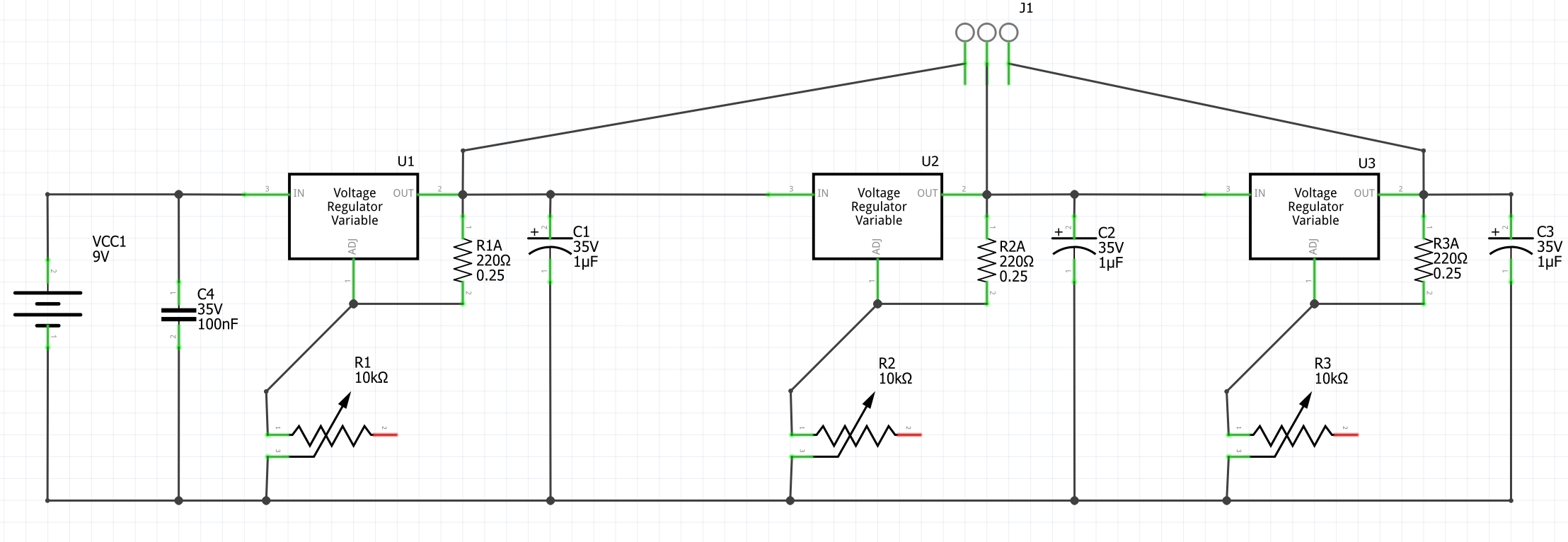
Below is a simplified circuit diagram with only three regulators, but you get the idea. The resistor values are placeholders. For the final product of course I'll use different values.
Nice approach.
Personally, I think: the caps on input and output are needed to avoid noise or even "oscillation".
I would consider every single LDO like a separate device, taking an input voltage and providing an output voltage, each LDO has its own caps (again).
It means: I would use on every single LDO an input and and output cap (even it looks "doubled"), never mind if you tap in between. These caps should be the right type (e.g. "low ESR types", see datasheet) and located very close to the pins of LDO. If you tap in between (you take the voltage there) - I would not care: every LDO is like a single separated LDO, getting a new input voltage.
Yes, the heat dissipation is now spread over all the LDOs: potentially they do not need anymore a heat sink (because the difference between in and out voltage is now small on every LDO).
BUT:
bear in mind: any LDO needs a minimum difference between in and out. Otherwise the voltage regulation cannot work!
You cannot do this:
5V -> 3V3 -> 3V0 -> 2V5 -> 2V -> etc.
some in-out-differences are below the minimum for LDO: I would assume: have at least 1V in-out difference between the LDOs, otherwise they cannot regulate. Check the datasheet for this minimum difference needed.
You can change your design into parallel structures, e.g:
5V -> 3V3
plus
5V -> 3V0
when 3V3 -> 3V0 with just 0.3V difference is too small for LDO. But now 5V -> 3V0 which is fine.
But 3V3 -> 3V0 is not large enough in difference (for LDO doing the regulation).
The capacitors are there to avoid noise and oscillation. The common rules are:
have the caps very close to the LDO pins
provide different values, e.g. a 10 micro plus a 1 micro (even plus a 10 or 100 nano) in parallel,
whereby the smallest cap value is closest to pin, e.g. this 10 or 100 nano is very close, the 10 micro can be a bit far away from pin):
"kill RF as closest to pin with the smallest cap value"
It has to do with "standing waves" on input and output: the total amount of caps do not matter just by itself: but when the current wave sees a cap to "kill" the standing wave, the smallest cap kills the highest frequency first. Different cap values (and sizes) have also different "impedance" for RF signals. Any LDO can generate or be sensitive for RF signals (therefore these caps), to avoid "wrong regulation" or oscillation.
So, take the caps seriously: every LDO has its own caps, never mind if a tap in between. And
split the total (sum) capacitance into different values and sizes (for RF issues). A large cap is bad
on RF: accompany this one with a smaller (e.g. 10...10nF) cap in parallel, the smallest shortest to LDO pin.
BTW:
I use this approach, to daisy chain LDOs also often in my design - it gives you also a better power supply ripple rejection (PSRR). But the main factor is: every LDO needs still this minimum
difference of in_out difference. Steps below this minimum will not work (the LDO will not regulate, it will not "work" and might bypass all the voltage and noise).
According to the datasheet, "Cadj is recommended to improve ripple rejection. It prevents amplification of the ripple as the output voltage is adjusted higher... Ci is recommended, particularly if the regulator is not in close proximity to the power-supply capacitors... Co improves transient response, but is not needed for stability."
So, for your application, I would think that (if your chained regulators are close together) a 1 uF tantalum Ci and a 10 uF tantalum Cadj for each regulator should suffice.
If, like drawn, you use a battery, then it is a waste to use power regulators. Instead use power converters.
If it is fed from a 50 Hz transformer, you need a much bigger cap at the vin of the first regulator (1000 uF).
Nothing bad. Within reason you can use much bigger capacitors without causing a problem. I would think 1000µF would be OK (but completely unnecessary).
Why are you using linear regulators rather then switching convertors? If, for example, you supply a 5V linear regulator from a 12V battery then imagine drawing a line on the battery 7 twelfths of the way along the length of the battery. That much of the battery is used only to make heat. Only the smaller part of the battery is supplying your load.
My capacitors are going to be about 1cm away from the regulator pins. Is running capacitors of different values in parallel that beneficial? Can I imagine it that the smaller capacitor reacts to fast ripple and the bigger one to big ripple?
Thanks.
I picked the first suitable variable regulator I found. I've done some more research and below is a LDO that's still relatively cheap:
As far as I understand I'd need to recalculate the resistors and potentiometers. The formula is very similar but not quite exactly the same.
The input is a standard 12V AC adapter.
For cost and convenience reasons. Like I said above, power efficiency is not my priority here.
I have an old Radio Shack electronics learning lab and I wanted to give it an upgrade and ditch the batteries and also add 12V, 5V, and 3V3, for Raspberry Pi and Arduino purposes. It's convenient to have all 9 voltages available at the same time. I did consider just buying a bench power supply but the ones in my budget have only one output.
If you're setting up a linear power supply, then "efficiency" is a false concept. It'll function by drawing the total current for all outputs from the 12V input, and the loss (as heat) will be the voltage drop to any given output, multiplied by the current drawn from that output, which has to add up to the same amount however you do it. All you can do is distribute the loss over the regulators. I don't know if oscillations in the system are likely.
That's exactly my goal. I want to avoid bulky and expensive heatsinks, and if I can do that by only changing the wiring of the regulators I consider that a success.
With that supply you could have 5volt/3Amp with a €2 switching stepdown regulator, or 3.3volt/5Amp, or a few hundred mA with a linear regulator setup. Your choice.
Leo..
Yes, a switching regulator (SPS) is better as an LDO (an LDO burns the voltage difference into heat). If you are not concerned about audio applications - SPS are much better (also in a daisy chain) They create just more noise in power rails, for digital fine, for audio it can become audible. And SPS can also "radiate" (EMI issues).
At least consider the Vin to Vout minimum difference needed - never mind what you use.
Regarding the caps on input and output, also for SPS: the datasheet might give you a clear hint which capacitors to use. Often, it is not just the capacity value, e.g. 10 micro plus 100 or 10 nano. They often talk about "low ESR" caps to use. The RF parameters of such cap matter, not just the value.
Electrolyte caps are often bad for RF performance (ESR value "wrong"). You have to accompany with low ESR caps (with smaller capacitance value).
Decide wisely which type of caps to use.
I assume you mean a fixed-voltage AMS1117 setup? If I only needed 12V, 5V, and 3V3, I'd probably do that. But I want 6 other outputs. Additionally, I don't need more than 1A. Unless I've made a mistake and adjustable switching regulators are available for cheap? If so, please link me.
No, a 1117, like the LM317 and LD1086, are all linear regulators.
A switching regulator has an inductor.
Search for "step-down converter" or "LM2596" on ebay.
Leo..
I dont quite understand why you want so many fixed outputs in the range between 12V and 1.5V.
Why not build it with daisy chained regs as you suggest fot the main voltages you want - 12V, 9V, 5V, 3V3
and a variable output controlled by a potentiometer?