Would someone mind having a look over this circuit and seeing what they think?
The purpose is to create a switched live which draws power from a battery using a switched live cable powering a tail light on a motorbike.
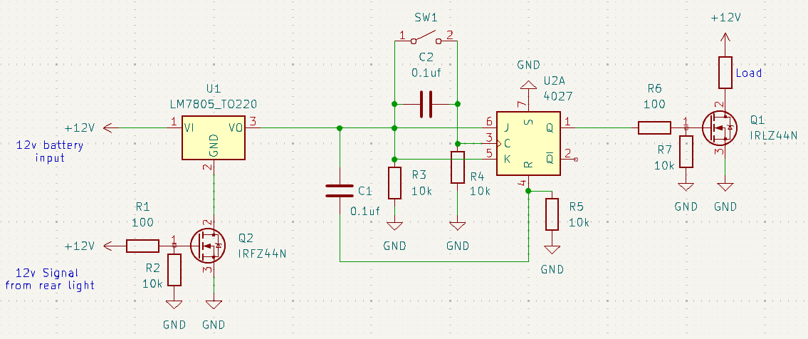
That then powers a voltage regulator to power a 4027 which I am hoping is configured as a toggle JK flipflop, with one output activating a transistor that will turn on some lights when I press a momentary switch. The 10k resistor/0.1uf cap on pin 4 is supposed to ensure the 4027 output always initiates in a low state.
Any feedback would be greatly appreciated.. I could probably do similar with less using an arduino or just running a 12v feed to the handlebars then to the lights but I'm trying to solve the problem using the above method if I can get it to work.
I would not recommend using the 7805 in that manner. When it does not have its bypass capacitors it does funny things. Also when the ground is not connected you are putting it in an undefined state and output is not predictable. I suggest you connect R2 to the other side of R1 then it is not a voltage divider.
Thanks for the reply guys. I forgot to put the caps either side of the 7805 - thanks for the heads up. I've added a 0.33uf on the input and 0.1uf on the output. The 4027 in kicad didn't have a pin 1
6 or 8 but they would be connected when I create the PCB. I've tested the whole circuit on breadboard and the 4027 on veroboard and it does work so I'm trying to ensure it's stability and reliable.
The first mosfet and 7805 would be powered up when the bike is turned on and they would stay on until the end of the journey. The second mosfet would be on every time I use full beam. With that in mind, is the 7805 going to ground important? I am aiming to use the output of the first mosfet to power an arduino at a later date (for a temperature display), so perhaps the answer to this is yes unless I use the regulated output?
R2 is acting as a pull down resistor, the arrow on the 12v should be the other way round, first time trialling kicad so I'm still working my way around the library.
A bit more info:
The main aim is to use a 12v switched live from the tail light of a motorbike to trigger the first mosfet so there is minimal effect to this light.
The purpose of creating the switched feed from the mosfet is so there's no parasitic drain on the battery from this circuit, I only need the circuit to work when the bike is on and I want that process to be initiated when the bike is powered up with the key rather than me having to turn it on manually.
When the switch connected to the 4027 is triggered, it activates the second mosfet and this sends a 12v signal to a relay which controls the full beam side of some bright LED fog lights. The reason for requiring reliability is I don't want them going off when I'm part way round a corner, and I don't want them unintentionally switching to full beam and blinding oncoming vehicles. I also can't easily tap into the 12v full beam 12v feed as the bike uses canbus.
The reason for the 7805 is because the bike's battery voltage can range from 12v to 14v so I wanted a clean input going into the 4027 to ensure the output is stable. The 7812 would be ok when the bike is at higher revs/14v but it would be too close to the output when at 12v. I went with the 5v instead of 7v or 9v as it meant I could use a logic level mosfet at the end of the circuit.
Hopefully this makes sense and I haven't complicated it further!
Hi Larry, I have a buck converter that I have tested and it works really well, I think I'm just being stubborn and trying to create the whole circuit on one board!