Circuit design for beacon-following robot

Hello,
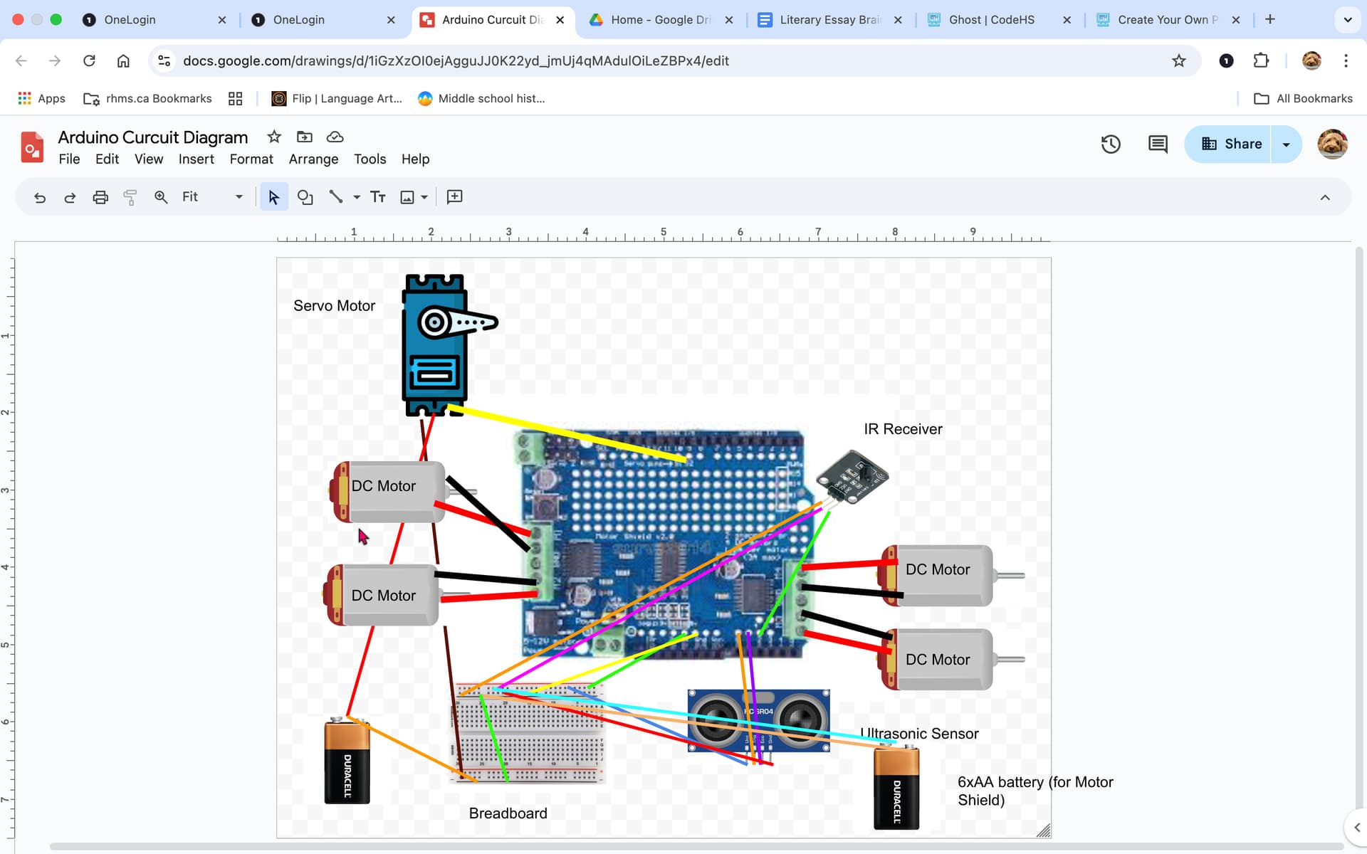
I am new to Arduino and electronics in general and this is my first circuit design. I am making a robot (Arduino Uno R3 + Adafruit Motor Shield V2) that is supposed to follow a wearable beacon through an IR transmitter and receiver. My servo was not turning, and it was receiving 9v. My friend told me that I should use another power source (so two) that is 4v designated for just my servo. The servo is used to turn the head of my ultrasonic sensor.


This is my first time creating a circuit diagram so please forgive me if it is messy. Thank you!

Servos normally run at 6V maximum so you may have damaged it

4V is almost certainly not enough and where are you getting 4V from ?

A 9V PP3 battery will not run your project for long as it cannot supply enough current

Sorry! The battery on the left is a 4xAA battery (I am using pictures I found on google to represent battery). The 9v battery I am using is 6xAA. I also changed the servo. Do you have any suggestions for changes?

A few pointers for next one...

  1. Label all pins on devices
  2. Do not use pictures, just draw a box with connection pins
  3. Only parallel connecting lines (do not cross lines)
  4. If lines "must" cross, draw no line and only label the pins to be connected

Thank you! I'll keep this in mind for next time!

Remember to not move the ultrasonic sensor until it receives an echo or times out. Other wise you cannot know the true distance or you might miss the echo.

Thanks for the suggestion! Overall, is my circuit ok? Would it work?

Define work? Have you tested it? Have you tested any of it? Can you make it work? How will you know if it works? How would I or anyone else know if it will work?
Please start putting your project together and begin testing!

Sorry for that question lol. I just tried to assemble it, and the I2C connection for my Arduino Uno and motor shield isn't working. Do you know what might be the problem? I soldered the headers connecting A4 and A5 (the SDA and SCL) along with all of the other headers. I ran an I2C test code and it does not sense any communication.

DO ONE CHANGE AT A TIME! And test that change. Since the I2C test code doesn't work, track down that problem before creating more problems.

Thanks for the suggestion! The I2C test code does work, it's just the I2C I think. I did a continuity test for each my SDA and SCL connection to test if my Arduino Uno and motor shield are communicating, and there is continuity. Do you know what could be the problem?

Does that include the board grounds? Did you test for continuity BETWEEN the wires and between each of them and the board ground?

Thanks for clarifying! I did these continuity checks:

  1. The GND connections between the Arduino Uno and motor shield are good :slight_smile:
  2. There's no short between SDA and SCL
  3. SDA and SCL aren't shorted to GND

Is there anything else I should check?

"Only two GPIO pins (SDA & SCL) plus 5v and GND are required to drive the multiple motors". Are you applying 5 volts to the board while testing? When all else fails, try different boards.

Thanks for the suggestions! I'm using a 6xAA battery to power the motor shield and I've confirmed continuity between the SDA, SCL, and ground connections on both the Arduino Uno and motor shield. The I2C test code was working fine before, but it stopped working after I added the independent 4xAA battery for the servo. Can this impact the I2C connection?

A depends! Did you connect the battery grounds to all the other grounds?

This is an indication that your wiring follows your confusing drawing.

Make a LEGIBLE drawing. Use parallel "wires" only. Start here...

                                        +---------+
                   +--------------------|- MOTOR2 |
                  +|--------------------|+        |
                  ||                    +---------+
                  ||                    +---------+
              +---||--------------------|- MOTOR1 |
             +----||--------------------|+        |
             ||   ||                    +---------+
         +--|+-|-|+-|--------------+
         |   M2 G M1           + + |
         |                     S S |
         |                     - - |
         |                  A5/SCL | 
         | + PWR            A4/SDA | 
         | - PWR              AREF | 
         |                     GND |--+ 
        -| IOREF           SCK/D13 |  |
        -| RST              DI/D12 |  | +---------+
        -| 3V3              DO/D11~|  | |  SERVO  |
        -| +5V                 D10~|  +-|-        |
        -| GND    Adafruit      D9~|----|S        |
        -| GND     Motor        D8 |  +-|+        |
        -| Vin    Shield        D7 |  | +---------+
        -|          V2          D6~|  |
        -| A0                   D5~|  v
        -| A1                   D4 |
        -| A2              INT1/D3 |
        -| A3              INT0/D2~|
        -| A4/DA  RS CK DI  TX>>D1 |
        -| A5/CL  GD D0 5V  RX<<D0 |
         |                         |
         |   M3 G M4               |
         +--|+-|-|+-|--------------+
             ||   ||                    +---------+
             ||   |+--------------------|- MOTOR3 |
             ||   +---------------------|+        |
             ||                         +---------+
             ||                         +---------+
             |+-------------------------|- MOTOR4 |
^ ^ ^ ^      +--------------------------|+        |
| | | |                                 +---------+
| | | |                                 +---------+
| | | |                                 |S  IRRX  |
+-|-|-|---------------------------------|+        |
| | | +---------------------------------|-        |
| | | |                                 +---------+
| | | |                                 +---------+
| | | +---------------------------------|-  SR04  |
| | +-----------------------------------|E        |
| +-------------------------------------|T  SR04  |
+---------------------------------------|+        |
                                        +---------+

My apologies for making an unclear circuit drawing. Thank you for the circuit diagram example you just made! I will try to do something like that next time.

Yes I did.

And when you put everything back to the way is was when it worked, does it work again?