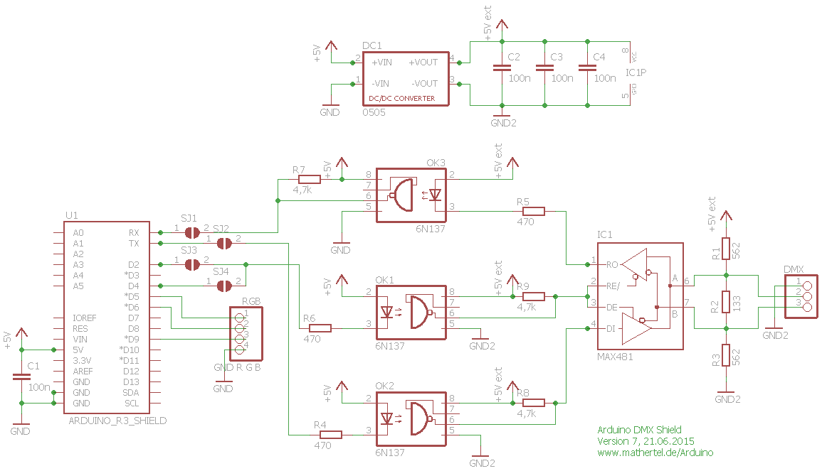
I need some help with a circuit I have designed. I am trying to make an isolated DMX controller, but it isn't working the way I expected. I have done something wrong, but I'm not sure what. I started with this design Mats Hertel and schematic. I only wanted to send DMX so I simplified the circuit to only send data. I have attached my schematic. I don't know how to put the image in-line. I have made some notes in the schematic. I'm sending serial data on the TX pin and hoping to turn it into isolated RS-485 data at the other end.
I've probed the circuit with a scope and I get a good signal at the UART, a good signal at the LED side of the optocoupler, and a good signal on the output of the optocoupler....UNLESS the output of the optocoupler is hooked up to the MAX485. It's like the optocoupler is being loaded down by the MAX485. I can almost see a signal when the two chips are connected, but it's such a low level it's almost like noise. Maybe 100mV. The 6n137 feels warm to the touch almost hot. I don't know if that's from the LED or the transistor.
I hope I've done something simple and someone can spot it. Thanks for reading this. I've probably left some details out, so let me know what other data I can provide. Thanks!
The resolution of the picture is low and the values dont show very well. How big is R3, R4? These are faol safe resistors and should be about 100k. R5 should much the transmission line impedance. Should be 120R for cat5 cable.
I was looking at some application notes from TI, and 560/133 seem to be recommended. Would the outputs of the 485 prevent the full swing on the output of the optocoupler?
Thanks Septillion. I've tried the circuit without the pull-up and pull-down on the output, and even wighout the 120 ohm termination resistor. On the optocoupler I've tried pull-ups as high as 500 Ohms and as low as 10k.
I have swapped the IC's a few times. I may be swapping too many things at once every time I try something new. These are prime new ICs from Mouser. I've tried the 6n137s with a function generator and they seem to work well on their own. I think I'll bypass the opto and see what happens if I feed the 485 directly from the UART. I'm scratching my head.
I may have solved this. I'm tracing back over my board layout and I may have a routing mistake. It looks like I may have a misplaced bit of copper between DE and DI on the 485. DE is pulled up to 5V, and if DI is high, it certainly explains all my problems (with this circuit anyway...).
I knew it was a stupid mistake. I thank everyone for looking at my circuit and providing help. I'll slice the offending trace and green-wire a solution and post here if it works.
