Circuit for USBASP to program an ATMega328P without bootloader

I'm new to ISP programming, so no doubt this will be easy for anyone with experience.

A couple of weeks ago, I made a small board with a 28-pin ZIF socket for burning a bootloader onto an ATMega328P chip using an Arduino UNO loaded with Nick Gammon's sketch written for the purpose.

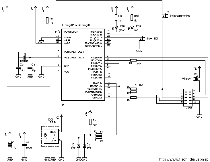
I got a USBASP programmer with a 10-pin socket today, and in working out it's connections I realised that the circuit to burn sketches to a chip without a bootloader looks the same as the circuit to burn a bootloader. Is this true, or am I missing something? My schematic is attached below.
Needless to say, I'm only talking about the RHS part of my schematic, with the USBASP replacing the UNO that's shown.

I'm aware that I'll first need to burn a bootloader on a brand new chip, to set the fuses, but am I otherwise good-to-go with the PCB I made? (My board already includes a 16MHz ceramic resonator.)

(Except I might make a new version of the PCB with a 10-pin header to suit the USBASP 10-pin socket.)

I've also attached a PIC of my PCB. If the circuit is the same for both, I wish I'd thought ahead and waited until I got my USBASP before making it. :frowning:

Bootloader burning board.JPG

I realised that the circuit to burn sketches to a chip without a bootloader looks the same as the circuit to burn a bootloader.

Yes, that's exactly the same. It's simply the method how to load any program to the Atmega.

(Except I might make a new version of the PCB with a 10-pin header to suit the USBASP 10-pin socket.)

I think, it's better to use 6-pin ICSP connector since there are unused pins on the 10-pin one. Arduino uses 6-pin and for the USBasp is able to buy reduction to 6-pin for a dollar on ebay. Moreover, if you have Arduino, you need not custom board for chip programming, just plug raw chip into the socket and program it with USBasp.

Budvar10:
Yes, that's exactly the same. It's simply the method how to load any program to the Atmega.

Excellent. I thought so, but just wanted confirmation.

I think, it's better to use 6-pin ICSP connector since there are unused pins on the 10-pin one. Arduino uses 6-pin and for the USBasp is able to buy reduction to 6-pin for a dollar on ebay.

I was planning on putting a 10-pin on my PCB because I already have 10-pin IDC headers sitting here, and the lead that came with the USBASP is 10-pin, so I don't need a 10-pin to 6-pin adaptor.

Moreover, if you have Arduino, you need not custom board for chip programming, just plug raw chip into the socket and program it with USBasp.

I made, (am making another), my own board so that i could include the ZIF socket for easier insertion/removal. I hate messing around getting chips in and out of standard dual-wipe DIL sockets, especially with my bad eyesight. I can't bend or break pins with a ZIF, and have plenty of time, 10-pin IDC headers, ZIF sockets, 16MHz ceramic resonators and blank pre-sensitised PCB material sitting here.

I know it's more work, and more money, but it suits me. :slight_smile:

And thank you very much for the reply. I didn't want to go ahead and make another board without confirming that I was on the right track.
And I won't even try to de-solder the ZIF socket, I'll use a new one and just throw the first board in the bin. I have plenty here that came cheap.
Now to quickly knock up a new board.....

Edit: Actually, just thinking, I do have one more question - I see that on the 10-pin socket on the USBASP lead, pins 4, 6, 8 and 10 are all marked GND in a scematic I found online, yet the circuit diagram I also found online for USBASP shows only pins 8 and 10 connected to GND, with pins 4 and 6 connected to TxD and RxD respectively on the USBASP ATMega88. (The TxD & RxD connections are what originally prompted me to start this thread.)
Just out of interest, do you know which is correct?
(Either way, just to be sure, I'll only connect pins 8 and 10 to GND on my board.)
I've attached both diagrams.

USBasp_schematics.pdf (14.3 KB)

If you have the USBasp then follow this: http://www.fischl.de/usbasp/bilder/usbasp_circuit.png, same as pdf you've posted.

Budvar10:
If you have the USBasp then follow this: http://www.fischl.de/usbasp/bilder/usbasp_circuit.png, same as pdf you've posted.

Thank you for that. I was suspicious of the other guy's diagram, with 4, 6, 8 and 10 all connected to GND.

Second diagram is correct. It is Atmel's standard. The USBasp is Mr. Fischel's product, it is his modification and to connect pins 4,6 eventually with GND is really bad idea in this case.

Budvar10:
Second diagram is correct. It is Atmel's standard. The USBasp is Mr. Fischel's product, it is his modification and to connect pins 4,6 eventually with GND is really bad idea in this case.

I appreciate the extra info. The diagram with pins 4,6,8 and 10 connected came from instructables.com, where a guy was showing how to make a 10-pin to 6-pin adaptor. Obviously, he shouldn't have his 'instructable' online at all, since it appears he dosn't really know what he's doing.
The web is a wonderful thing, but any info found online needs to be carefully screened to separate the good stuff from the bullshit. :slight_smile: And unfortunately, often the bullshit seems easier to find. :frowning:

OldSteve:
I appreciate the extra info. The diagram with pins 4,6,8 and 10 connected came from instructables.com, where a guy was showing how to make a 10-pin to 6-pin adaptor. Obviously, he shouldn't have his 'instructable' online at all, since it appears he doesn't really know what he's doing.

An all too common observation.

OldSteve:
The web is a wonderful thing, but any info found online needs to be carefully screened to separate the good stuff from the bullshit. And unfortunately, often the bullshit seems easier to find.

You can find it easily on Google. :grinning:

Actually, Google helps you a lot really. "instructables" has a bit of a bad name around here - but even the references on this website contain some bad blunders. :astonished:

The thing is, if you are going to be working with Arduinox, the 6-pin IDE connector is the common standard so it would be wise to plan on that - even if you conveniently happen to have some 10-pin connectors. Most of us (but not all) would have little or no experience with Atmel dev boards using the 10-pin connector.

Paul__B:
An all too common observation.
You can find it easily on Google. :grinning:

Ha, yeah.

Actually, Google helps you a lot really. "instructables" has a bit of a bad name around here - but even the references on this website contain some bad blunders. :astonished:

And yes again. :slight_smile:

The thing is, if you are going to be working with Arduinox, the 6-pin IDE connector is the common standard so it would be wise to plan on that - even if you conveniently happen to have some 10-pin connectors. Most of us (but not all) would have little or no experience with Atmel dev boards using the 10-pin connector.

Of course you're right. I think what I'll do is quickly bang up a 10-pin version, just to get me in business straight away, and order some 6-pin IDC headers and sockets on eBay. When they (eventually) arrive, or when I need it, I'll make up a new board and a 10-pin to 6-pin cable. Then I'm covered for all eventualities. I actually have a small, cheap Chinese dev board coming, and it does have a 10-pin connector.
I want to use it tomorrow, but the 6-pin connectors will take a few weeks to get here if I buy cheap ones from eBay. China is 'just around the corner' from me here in OZ, but postage is slow.

I've attached a pic of the little dev board that's coming. Cost about $2 on eBay.

Dev board.JPG

OldSteve:
I've attached a pic of the little dev board that's coming. Cost about $2 on eBay.

dc24c44c41aff00d85123d534c2677c6b5d8c223.jpg
Oooh yeah! I bought one of those myself and have assembled it. Not sure what to do with it yet but it certainly looked pretty and was pretty cheap ...

I have bought a fair few of the "Dupont" jumper leads (ribbons) and the various multiple housings - two-way, three, four, five and three by two - which latter is of course, the one for the I(C)SP. So can make up nice programming adapter leads using these rather than IDC ribbon connectors. The outer housing (and polarity key) is a part of the board connector on the 10-pin boards such as that one, but not on the Arduinox.

Paul__B:
dc24c44c41aff00d85123d534c2677c6b5d8c223.jpg
Oooh yeah! I bought one of those myself and have assembled it. Not sure what to do with it yet but it certainly looked pretty and was pretty cheap ...

I have bought a fair few of the "Dupont" jumper leads (ribbons) and the various multiple housings - two-way, three, four, five and three by two - which latter is of course, the one for the I(C)SP. So can make up nice programming adapter leads using these rather than IDC ribbon connectors. The outer housing (and polarity key) is a part of the board connector on the 10-pin boards such as that one, but not on the Arduinox.

At $2, mine is already pre-assembled. Another case of "how do they do it so cheap".
I'll get a bunch of the 6-pin connectors, for my future boards. Most of my projects will have an ATMega328P on a custom board, so if I feel that I might be re-programming them in the future, a 6-pin takes up less space.

I've finished the PCB layout for my new board with the 10-pin connector. Just need to print a transparency and get on with actually making it now. (Gonna be a late night - it's almost midnight now.)

2x3 header is all you need. That's what Atmel used on their AVR ISP MKii programmer. That's all I put on my boards, just like an Uno or Mega.

I've only found 2x3 IDC crimp on connectors at mouser.

Very easy to use 6 discrete wires and two headers to make a 10-pin to 6 pin adapter:
2x3

2x5

wires
male-female, or female-female if that's what your programmer has

See attached for an example.

CrossRoads:
2x3 header is all you need. That's what Atmel used on their AVR ISP MKii programmer. That's all I put on my boards, just like an Uno or Mega.

Or Nano etc. ...

I note that apart from multiple grounds, the other active pins are serial Tx and Rx. To operate with a bootloader?

CrossRoads:
2x3 header is all you need. That's what Atmel used on their AVR ISP MKii programmer. That's all I put on my boards, just like an Uno or Mega.
http://www.atmel.com/webdoc/avrispmkii/index.html
I've only found 2x3 IDC crimp on connectors at mouser.
http://www.mouser.com/ProductDetail/FCI/71600-006LF/?qs=sGAEpiMZZMs%252bGHln7q6pm24n0txessAMv97Wpyh9hZc%3D
Very easy to use 6 discrete wires and two headers to make a 10-pin to 6 pin adapter:
2x3
https://www.pololu.com/product/1911
2x5
https://www.pololu.com/product/1913
wires
male-female, or female-female if that's what your programmer has
Pololu - Wires with Pre-Crimped Terminals 50-Piece 10-Color Assortment M-F 3"
See attached for an example.

Yep, I know how to make an adaptor cable. And as stated, My programmer(s), two now, came with a 10-pin cable and so did my dev board, so It's still handy to have the board that I made with a 10-pin header.

When I need it, ie if I ever buy a dev board with 6-pin connector or an AVRISP II etc, then I can easily knock up a board with a 6-pin connector.

But for now, with the equipment that I have, a 6-pin connector isn't needed at all. If I had one, I couldn't use it, since everything is 10-pin. It may not be what you and others have, but it is what I have.

I don't actually foresee ever buying an AVRISP II programmer, since the USBASP works fine, and I probably won't ever buy another dev board either. I'd prefer to make my own boards.

Paul__B:
Or Nano etc. ...
I note that apart from multiple grounds, the other active pins are serial Tx and Rx. To operate with a bootloader?

Good question I was wondering too, and came to the same conclusion.

Edit: And I do have two boards with 2x3 headers of course - my UNOs, but I don't plan on using them.

those two serial pins are supported by chinese firmware but not "fischel" version. unfortunately docs and source never translated from chinese so wild west hobbyists rarely able to take advantage. chinese firmware fixed other bugs which we can benefit by simply buying cheepo ebay usbasp.

john1993:
those two serial pins are supported by chinese firmware but not "fischel" version. unfortunately docs and source never translated from chinese so wild west hobbyists rarely able to take advantage. chinese firmware fixed other bugs which we can benefit by simply buying cheepo ebay usbasp.

Thanks for that, John.
And mine are certainly cheapos - AU$2.56 for the first, (USBASP), then AU$7.48 for the second, (USBASP USBISP), with a ZIF socket dev board included.

yes, fantastic deals. i love these usbasp dongles. after struggling for years with isptiny, pony, mkII, dragon, etc it was like a breath of fresh air. lets not even mention those damn pickit and other scams. and for as low as a buck and change these usbasp make excellent little general purpose controller when re-flashed with custom code. may or may not take advantage of the built in usb interface.

i like arduino-as-isp programmer idea too. hard to beat picking up a 30 sent mega8 with a few pins added and being able to program just about any avr out there. you do need a serial/usb converter but thats a prerequisite for any serious hobbyist anyway,

john1993:
yes, fantastic deals. i love these usbasp dongles. after struggling for years with isptiny, pony, mkII, dragon, etc it was like a breath of fresh air. lets not even mention those damn pickit and other scams. and for as low as a buck and change these usbasp make excellent little general purpose controller when re-flashed with custom code. may or may not take advantage of the built in usb interface.

i like arduino-as-isp programmer idea too. hard to beat picking up a 30 sent mega8 with a few pins added and being able to program just about any avr out there. you do need a serial/usb converter but thats a prerequisite for any serious hobbyist anyway,

I haven't got as far as custom programming a USBASP yet, (I just started with Arduino a few weeks ago), but I can see where it would be handy.
I looked at the AVRISP II and it's cost, then looked at the USBASP and quickly made up my mind. :smiley:

And no shortage of USB to TTL converters here, I had about 20 at last count. 3 running on my PC as I type, connected to APC220 RF modules to communicate with my various PIC-based gadgets. (Bedroom alarm clock, workshop alarm system and a Mattel Mindflex headset hack.)

And you can always go extreme and use a standalone programmer, put your .hex file on SD card and program via the ICSP header, battery or wallwart powered. Can be used to program 3.3V or 5V systems, selecting 1 of 256 files from the SD card via rotary encoder. I have a similar card to select 1 of 16 with a push button for 5V only systems.