I've assigned myself the brief to design and build a 12v fan controller circuit using only readily available electronic components from my local hobby dealer. No pre-built modules, and on the pro-mini platform.
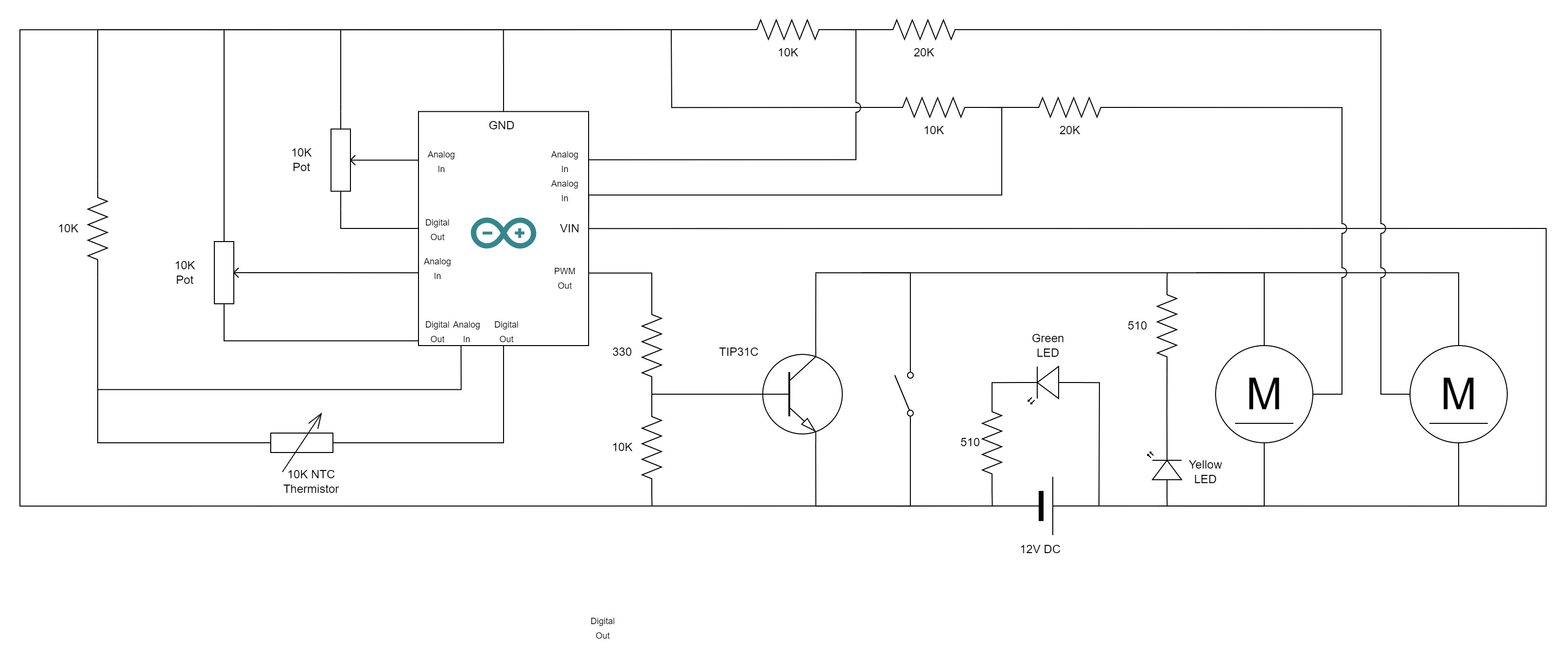
I've got the prototype done and working. It has some dials I can use to set fan-on temp and the temp at which fan reaches 100%, scaled linearly. There's also an override switch to set the fans to 100%. The code part works fine and I'm comfortable with that, however before I get to soldering I'd like some opinions on whether the circuit design is sound and whether any component could be improved. I've attached a schematic, apologies if I didn't adhere to any conventions, it's not my specialty. The unmarked pins on the Mini are just analog or digital. Vin is the Raw input.
Is my base resistor suitable, based on an approx 600ma load on the collector? I considered the idea of using a MOSFET but it just seems more complicated?
I fried the voltage regulator on the pro-mini while attempting to measure voltage across the Green LED. Why though? Is there any reason that would occur or is it most likely I touched something else with the probe? I'm back to using externally regulated 5v for the board until a replacement arrives.
I haven't tested the override switch yet. Is there any potential issues with applying a 12v load between the emitter and collector while it's closed?
Green and yellow LEDs backwards. They always "point" to more negative circuit potential.
It was hard to spot, because conventional schematic best practices are to have + top of sheet, - at bottom. Would also be much clearer if you labelled each pin (function, not necessarily pin number) of the Arduino, for clarity.
Without labels, your thermistor wiring is incomprehensible, though it looks "wrong".
1 - can't say, haven't worked with TIPs in a lonnnnggg time.
2 - likely, you shorted something.
3 - not really, though it's uncommon practice. More common might be to provide an alternate feed to the transistor base.
You really should consider the Mosfet.
Your two motors likely need reverse-snubbing diodes to damp transients. Band side of diode to positive motor terminal.
Is that actually a motor control circuit, though? With PWM input? Links to online specs for the motor, please.
It doesn't take much effort to learn the fundamentals, and conventions are exactly what makes an international language like schematic circuit diagrams useful. Failure to learn and adhere to them makes your effort almost useless. This tutorial covers most of the bases.
As noted, pin and connection designations are required. What is "M" and what are its pinouts and specifications? Post a link to it.
You must know and understand those specifications in order to choose a driver transistor and associated circuitry.
I fixed up the LED directions and labelled pins, thanks for that. Hopefully it's clearer. The M symbols are just 3 pin computer fans, which I am lead to believe have diodes built in although I can't be sure as they're just old PC fans I had kicking around.
I saw that you edited your first post, after I edited my first post. But not to edit my subsequent posts I will reply anew.
3 - not really, though it's uncommon practice. More common might be to provide an alternate feed to the transistor base.
So for example a better way to do the override would be to have an output on the arduino, connected to the base, set it to high and stick the toggle switch on that?
Not if you course-correct quickly enough! But seriously, it's a 'thing' here. There's no shame in posting the new rev, if anything it proves you're listening, which is sometimes difficult to discern otherwise. Same with code, always post complete sketches, and when you modify, just put up a new posting describing what you did and why. Makes for a good flow in the thread, and anyone can pick up at that point (though it often still helps to pick up the backtrail from the start).
Hang in there, you'll do fine. Great start, giving allowance for schematic-norm-ignorance!(and yeah, you busted me, I did do that. Oh well.)